Energy storage striking device and mechanical remote brake system

A release mechanism and locking mechanism technology, applied in the direction of valve device, mechanical equipment, valve operation/release device, etc., can solve the problems such as the large force required for the brake handle, the risk of overrunning, and the untimely action, etc., to achieve Improve the response speed of equipment failure, reduce the number of directly involved personnel, and achieve high reliability

Pending Publication Date: 2021-12-10
CHINA GENERAL NUCLEAR POWER OPERATION +2
View PDF7 Cites 0 Cited by
  • Summary
  • Abstract
  • Description
  • Claims
  • Application Information

AI Technical Summary

Problems solved by technology

[0005] (1) The speed of the steam-driven pump is very high when it is overspeed, and there is a risk of running away;
[0006] (2) The pump room is narrow and it is difficult for personnel to escape;
[0007] (3) The steam pump itself runs at super high speed when overspeeding, the temperature of the pump body is high, and steam (above 200°C) will be ejected when the brake is switched on, which may injure people;
[0008] (4) When speeding, the noise is very loud (about 100-120 decibels, and the noise level exceeding 100 decibels is unbearable), which has a great impact on personnel's psychological endurance and hearing loss, and communication is difficult;
[0009] (5) The response of the personnel to manually push the brake handle is slow, and the action is not timely; if the overspeed brake is not timely, there is a risk of equipment damage; sometimes the brake handle requires a large force, and the staff may not be able to take it off for the first time.

Method used


Image

  • Energy storage striking device and mechanical remote brake system
  • Energy storage striking device and mechanical remote brake system
  • Energy storage striking device and mechanical remote brake system

Examples


Embodiment Construction

[0052] In order to have a clearer understanding of the technical features, purposes and effects of the present invention, the specific implementation manners of the present invention will now be described in detail with reference to the accompanying drawings.

[0053] The mechanical remote brake system of the present invention is used to remotely brake the steam-driven pump, avoiding problems and various safety risks caused by manual brakes performed by staff at close range.

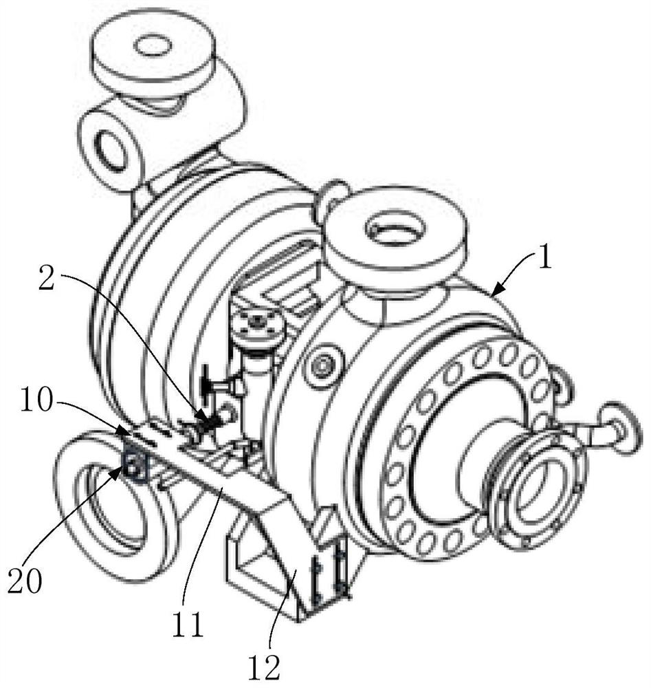
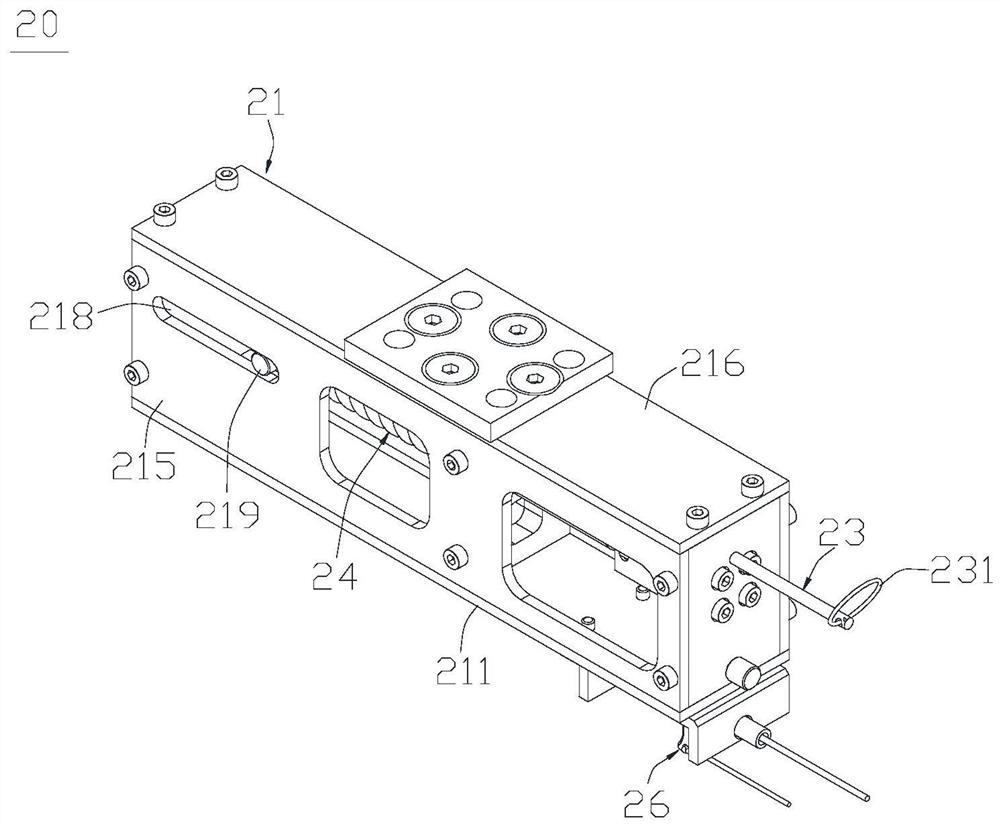
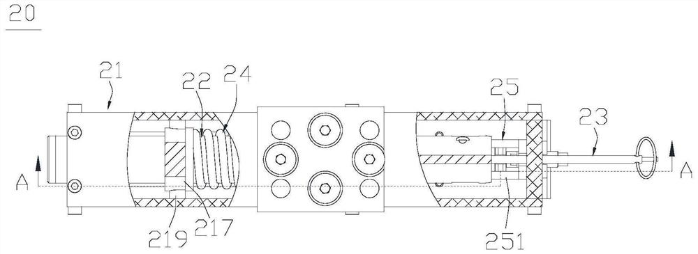
[0054] like figure 1As shown, the mechanical remote braking system of the present invention may include a mounting bracket 10 installed on the pump body 1 of the turbopump, an energy storage striking device 20 fixed on the mounting bracket 10, and an energy storage striking device 20 Connected gravitational transmission lines (not shown). On the mounting bracket 10 , the energy storage striking device 20 is directly opposite to the brake handle 2 on the pump body 1 , and the distance between the two is ...


PUM


Abstract

The invention discloses an energy storage striking device and a mechanical remote brake system. The energy storage striking device comprises a support, a striking rod, a pull rod, a force storage spring, a locking mechanism and a releasing mechanism; the striking rod is provided with a striking end and a connecting end which are opposite, the striking rod is arranged in the support in a penetrating mode and can move back and forth in the axial direction, and the end portion of the striking end is located on the outer side, facing the brake striking handle, of the support; the striking rod is sleeved with the force storage spring; the pull rod is axially connected with the connecting end of the striking rod, extends out of the outer side, back on to the brake handle, of the support and is used for pulling the striking rod to axially move and compressing the force storage spring; the locking mechanism is arranged in the support and located on one side of the connecting end, and the releasing mechanism is connected with the locking mechanism. According to the energy storage striking device and the mechanical remote brake system, the striking rod is driven to strike the brake striking handle on the steam turbine pump in a spring force storage mode, external energy is not relied on, the mechanical triggering reliability is high, and the influence of the environment and the working condition is avoided; and remote switching is realized, so that direct participants in the overspeed test of the steam-driven pump are reduced, and the equipment fault response speed is increased.

Description

technical field [0001] The invention relates to the technical field of nuclear power equipment, in particular to an energy storage striking device and a mechanical remote braking system. Background technique [0002] The normal operating speed of the steam-driven auxiliary feedwater pump in nuclear power plants is 8000r / min. The pump is equipped with two overspeed protection devices. The first level overspeed protection is electromagnetic overspeed protection, and the set operating speed range is 9250-9420r / min; The protection is mechanical overspeed protection, and the set action speed range is 9675-9850r / min. [0003] According to the requirements of the nuclear power plant operation supervision program, the steam-driven auxiliary feedwater pump (short for steam-driven pump) needs to perform an electromagnetic and mechanical overspeed protection test every time it is overhauled. When performing the mechanical overspeed protection test, the electromagnetic overspeed protec...

Claims


Application Information

Patent Timeline
Patent Type & Authority Applications(China)
IPC IPC(8): F16K31/46F16K31/62
CPCF16K31/465F16K31/62
Inventor 刘闯铭邢兴龙杨忠司晓贞王禹
Owner CHINA GENERAL NUCLEAR POWER OPERATION
Why Eureka
Try Eureka