Handheld laser radar scanner

A laser radar and scanner technology, applied in the field of laser radar, can solve problems such as inability to achieve the effect of increasing the scanning area

Pending Publication Date: 2021-12-10
武汉天眸光电科技有限公司
View PDF0 Cites 2 Cited by
  • Summary
  • Abstract
  • Description
  • Claims
  • Application Information

AI Technical Summary

Problems solved by technology

[0003] The main purpose of the present invention is to propose a hand-held laser radar scanner, which aims to solve the problem that the laser scanning area of ​​the existing laser radar scanning system is fixed, so it cannot be used in a wider scanning area.

Method used


Image

  • Handheld laser radar scanner
  • Handheld laser radar scanner
  • Handheld laser radar scanner

Examples


Embodiment Construction

[0031] The following will clearly and completely describe the technical solutions in the embodiments of the present invention with reference to the accompanying drawings in the embodiments of the present invention. Obviously, the described embodiments are only part of the embodiments of the present invention, not all of them. Based on the embodiments of the present invention, all other embodiments obtained by persons of ordinary skill in the art without creative efforts fall within the protection scope of the present invention.

[0032] It should be noted that if there is a directional indication (such as up, down, left, right, front, back...) in the embodiment of the present invention, the directional indication is only used to explain the position in a certain posture (as shown in the accompanying drawing). If the specific posture changes, the directional indication will also change accordingly.

[0033] In addition, if there are descriptions involving "first", "second" and ...


PUM


Abstract

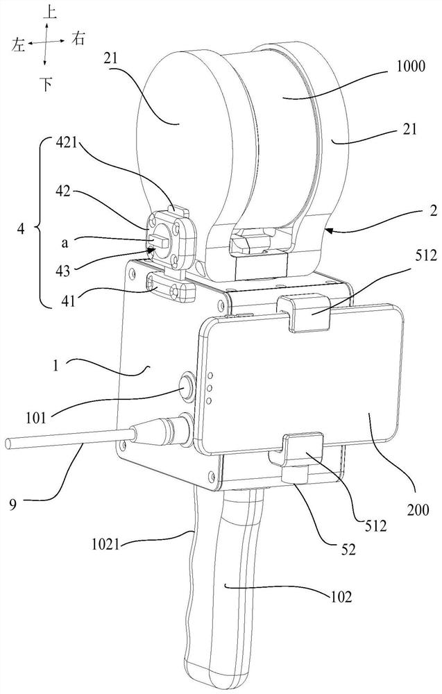
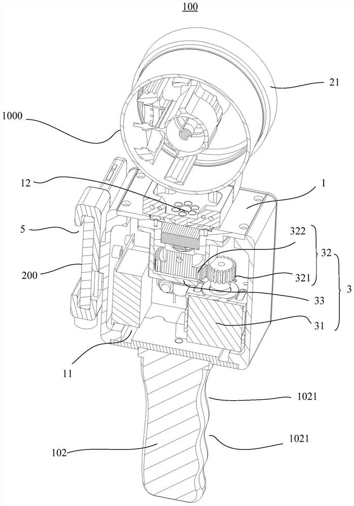
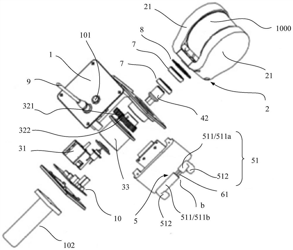
The invention discloses a handheld laser radar scanner. The handheld laser radar scanner comprises a shell, a mounting frame and a driving assembly, a mounting cavity is formed in the shell, a mounting hole is formed in the upper end face of the shell in a penetrating mode, the mounting hole communicates with the mounting cavity, and the mounting frame is rotationally mounted on the upper end face of the shell along the vertical axis; the mounting frame is provided with two mounting arms which extend in the up-down direction and are oppositely arranged at intervals in the left-right direction, the space between the two mounting arms is used for allowing the laser radar to be rotationally mounted along the axis in the left-right direction, and the driving assembly is mounted in the mounting cavity and provided with a driving shaft extending in the up-down direction; the driving end of the driving shaft extends out of the mounting hole to be in driving connection with the mounting frame, so that the laser radar can rotate along the left-right axis and can rotate along the up-down axis, the scanning area of the handheld laser radar scanner is enlarged, and the handheld laser radar scanner is suitable for being used in a wide scanning area.

Description

technical field [0001] The invention relates to the technical field of laser radar, in particular to a hand-held laser radar scanner. Background technique [0002] The lidar scanning system is a device that uses laser beams to perceive surrounding objects, and reflects the position and shape of surrounding objects in the form of point cloud data. The laser scanning area of ​​the laser radar scanning system in the prior art is fixed, so it cannot be applied to a wider scanning area. Contents of the invention [0003] The main purpose of the present invention is to propose a hand-held laser radar scanner, which aims to solve the problem that the laser scanning area of ​​the existing laser radar scanning system is fixed, so it cannot be used in a wider scanning area. [0004] In order to achieve the above object, the handheld lidar scanner proposed by the present invention includes: [0005] The housing is formed with an installation cavity, the upper end surface of the hou...

Claims


Application Information

Patent Timeline
Patent Type & Authority Applications(China)
IPC IPC(8): G01S7/481
CPCG01S7/4817
Inventor 程刚官超
Owner 武汉天眸光电科技有限公司
Why Eureka
Try Eureka