Eureka AIR delivers breakthrough ideas for toughest innovation challenges, trusted by R&D personnel around the world.

Large-scale motor global thermal field and fluid flow field calculation method based on three-dimensional model boundary coupling

A large-scale motor and three-dimensional model technology, which is applied in the direction of design optimization/simulation, special data processing applications, etc., can solve problems such as difficult convergence of iterations, large structural size of large motors, and excessive calculation, so as to solve the difficulty of convergence and save construction The effect of model time and iterative calculation time

Active Publication Date: 2021-12-10
CHINA THREE GORGES CORPORATION
View PDF2 Cites 0 Cited by
  • Summary
  • Abstract
  • Description
  • Claims
  • Application Information

AI Technical Summary

Problems solved by technology

However, as the types, structures and capacities of motors increase, on the one hand, it is difficult to determine whether the local thermal field and flow field are the hottest parts of the motor; on the other hand, simply building a local model will cause the flow field to appear Large changes, it is difficult to simulate the actual operation
[0003] The structural size of large motors is relatively large. Establishing a three-dimensional overall motor model in the entire domain to calculate the flow field and thermal field will cause problems such as excessive calculation, slow calculation, and difficult convergence of iterations.
Establishing a local model based on the symmetry of the motor structure and the ventilation system in the state of uniform rotation will make the calculation model simple and difficult to reflect the real distribution of the motor flow field and thermal field

Method used


Image

  • Large-scale motor global thermal field and fluid flow field calculation method based on three-dimensional model boundary coupling
  • Large-scale motor global thermal field and fluid flow field calculation method based on three-dimensional model boundary coupling
  • Large-scale motor global thermal field and fluid flow field calculation method based on three-dimensional model boundary coupling

Examples


Embodiment Construction

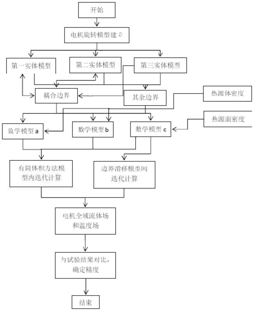
[0094] Such as figure 1 As shown, the calculation method for the global thermal field and fluid flow field of a large motor based on the boundary coupling of the solid model includes the following steps:

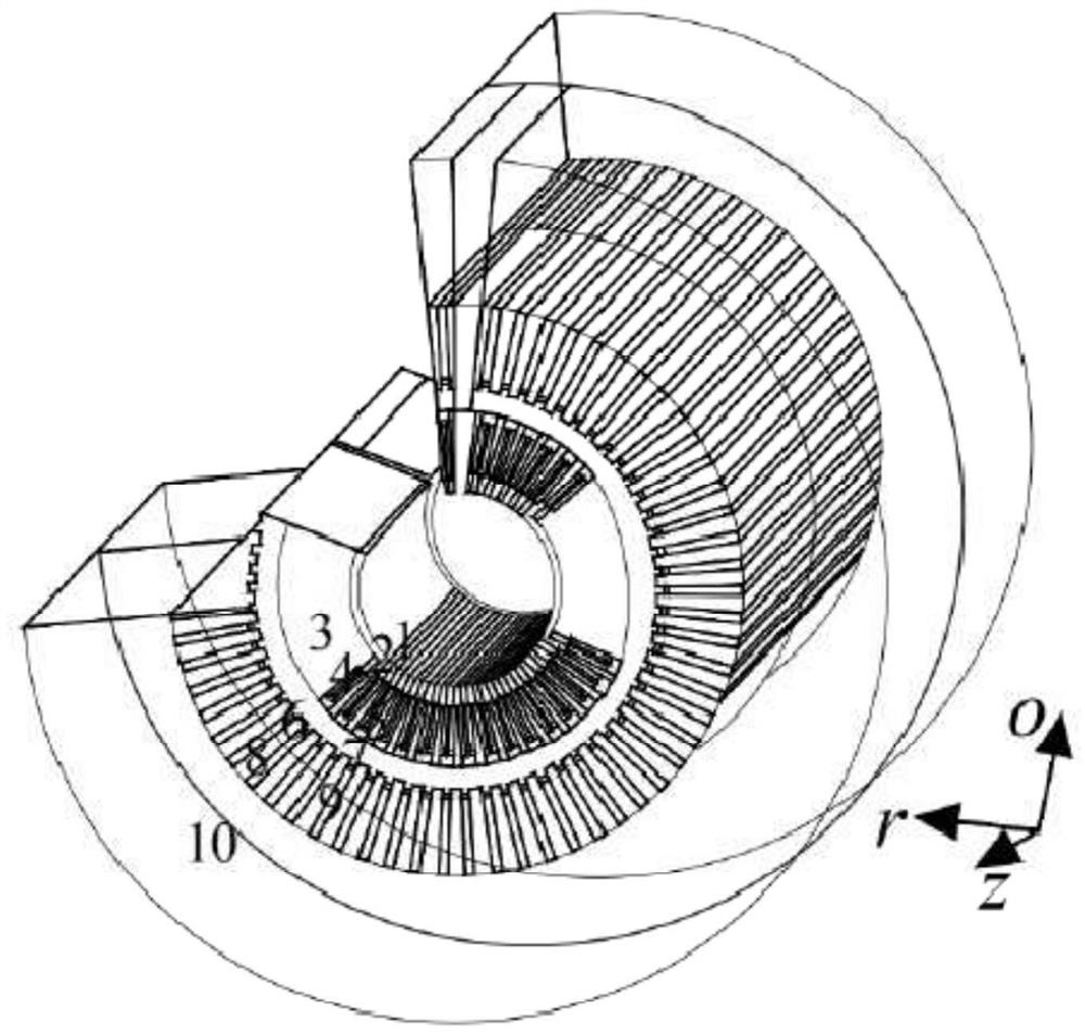
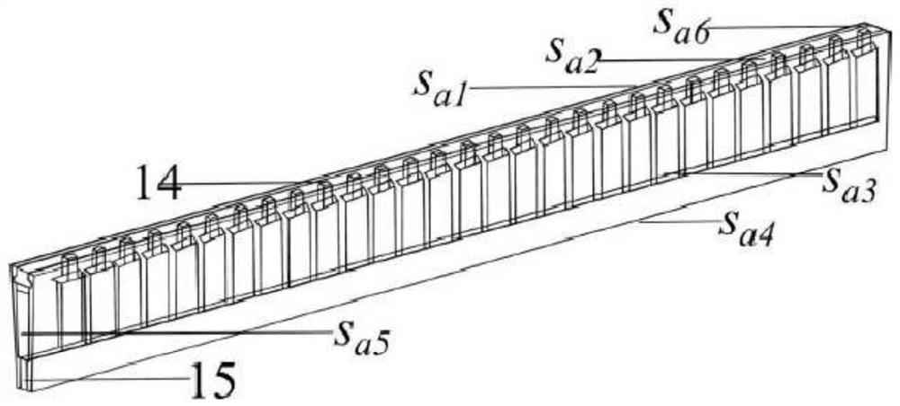
[0095] Step 1: According to the symmetry of the motor structure and the ventilation system in the state of uniform rotation, establish the solid model of the rotor region of the half axial section, the solid model of the stator and the air gap region of the half axial section, and the full position of the axial center Circumference solid model.

[0096] Step 2: According to the coupling relationship of the three solid models, set reasonable boundary conditions for the three solid models.

[0097] Step 3: Using the mathematical model of fluid and heat transfer, calculate the global thermal field and fluid flow field of the motor.

[0098] Step 4: Compare the established calculation model with the experimental results to verify the accuracy and precision of the calculation m...


PUM


Abstract

The invention discloses a large-scale motor global thermal field and fluid flow field calculation method based on three-dimensional model boundary coupling. The method comprises: according to the symmetry of the motor structure and the ventilation system in the constant-speed rotation state, establishing three entity models: a rotor area entity model of a half axial section, a stator and air gap area entity model of a half axial section, and a full-circumference entity model of an axial center position; according to the coupling relation of the three entity models, setting boundary conditions for the three entity models, including a periodic boundary condition, a heat dissipation boundary condition, a heat insulation boundary condition and a boundary condition of a ventilation inlet and a ventilation outlet; and calculating a motor global thermal field and a fluid flow field by adopting a fluid and heat transfer mathematical model. According to the method, the constant-speed rotation state of the motor is considered, and the global flow field and the thermal field of the motor are calculated by setting the coupling boundary conditions, so that the accuracy and the speed of calculation are ensured. Practical application in engineering is facilitated.

Description

technical field [0001] The invention relates to the technical field of motor design, in particular to a calculation method for the global thermal field and fluid flow field of a large motor based on boundary coupling of a three-dimensional model. Background technique [0002] The iterative calculation of the flow field and thermal field of the motor using the finite volume method has gradually been applied in the field of motor design. Large motors are limited by their volume. When the finite volume method is used to calculate the flow field and thermal field, the establishment of the overall model of the motor will make it difficult to converge in the subdivision and calculation iterations. Therefore, based on the symmetry of the motor structure and ventilation structure, a local model is usually established to study the local thermal field and flow field. However, as the types, structures and capacities of motors increase, on the one hand, it is difficult to determine whe...

Claims


Application Information

Patent Timeline
Patent Type & Authority Applications(China)
IPC IPC(8): G06F30/20
CPCG06F30/20Y02E60/00
Inventor 苏营邹祖冰刘喜泉孙勇刘瑞阔周登科
Owner CHINA THREE GORGES CORPORATION
Why Eureka
Eureka Blog
Learn More