Automatic optical identification system for vehicle profile

An automatic optical and identification system technology, applied in the field of vehicle detection, can solve the problems of reducing accuracy, difficult for drivers to drive, unable to identify the number of tires, etc., to reduce the impact, improve the detection accuracy, and avoid the hidden danger of overloading.

Active Publication Date: 2021-12-10
成都古河云科技有限公司
View PDF42 Cites 2 Cited by
  • Summary
  • Abstract
  • Description
  • Claims
  • Application Information

AI Technical Summary

Problems solved by technology

[0006] Each axle of a truck may have single tires, twin tires, etc. The types of axles and wheels are different, and the allowable load is also different. The current axle identification equipment can only identify the number of axles, but not the number of tires on each axle.
[0007] The existing detection environment is open detection. When the vehicle is detected, it is easy to be affected by weather such as rain, snow, fog, etc., which greatly reduces the accuracy.
[0008] Different detection occasions have different requirements for the height of the vehicle. However, the existing detection equipment usually uses a fixed height limit pole to limit the height, which is not universal.
[0009] When the visibility is low at night, the driver is not easy to drive, and may drive into the detection system, causing safety hazards and economic losses

Method used


Image

  • Automatic optical identification system for vehicle profile
  • Automatic optical identification system for vehicle profile
  • Automatic optical identification system for vehicle profile

Examples


Embodiment

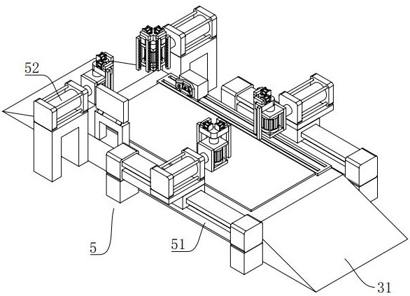
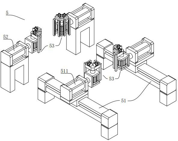
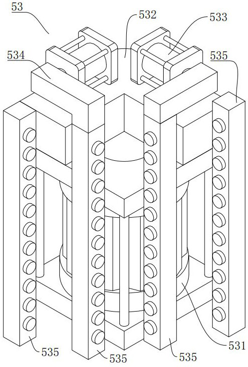
[0046] Such as Figure 1-Figure 12 The shown automatic optical recognition system for vehicle outline includes a recognition room 1 , a lane 2 , a driving unit 3 , a wheel axle recognition unit 4 , and an optical recognition unit 5 .

[0047] In this embodiment, the first linear mechanism 13 is the first rodless cylinder, the second linear mechanism 51 is the second rodless cylinder, the third linear mechanism 511 is the third single-axis linear cylinder, and the fourth linear mechanism 52 is The fourth uniaxial linear cylinder, the fifth linear mechanism 533 is the fifth uniaxial linear cylinder, and the rotating mechanism 531 is a rotary motor. The first optical reflector assembly 14 is a first infrared reflector, and the second optical reflective assembly 535 is a second infrared reflector.

[0048]The identification room 1 includes a closed room, and an electrically connected computer and a camera are suspended from the top of the closed room. The two ends of the closed ...


PUM


Abstract

An automatic optical identification system for a vehicle profile comprises an identification room, lanes, a driving unit, a wheel axle identification unit and optical identification units. The lanes are arranged at two ends of the identification room. The driving unit is arranged in the identification room. The upper end face of an identification table is provided with a wagon balance. The axle recognition unit comprises a C-shaped frame, whereina plurality of laser axle identifiers arranged on one side face of the C-shaped frame. The optical identification units are arranged on the two sides of the driving unit, one end of an output shaft of the third linear mechanism is provided with an optical mechanism, and one end of an output shaft of the fourth linear mechanism is also provided with an optical mechanism.The optical mechanism comprises a rotating mechanism which is vertically arranged; two second optical correlation assemblies on one side of a right-angle plate and two second optical correlation assemblies on the other side of the right-angle plate have a preset height difference so that light paths on the two sides can be staggered. According to the invention, automatic and accurate detection is realized, joint cheating of detection personnel and drivers is avoided, overload hidden dangers are avoided, the influence of weather on detection is reduced, the universality of equipment is improved, and traceability of related records is realized.

Description

technical field [0001] The invention relates to the field of vehicle detection, in particular to an automatic optical recognition system for vehicle outlines. Background technique [0002] In recent years, with the expansion of the road transportation market, highways, national highways, provincial highways and other roads, as well as industrial parks, internal roads and entrances and exits of overruns and overloading have been repeatedly banned. It is backward and consumes a lot of manpower and material resources, and there are many problems in the current detection. [0003] When inspecting the length and width of different models, there are different error standards in various regions, allowing vehicles to exceed the standard limit length and width within 1% to 3%. However, the regulations that allow errors make the inspectors and drivers Sometimes there is a case of joint cheating, since the error part is usually measured manually. [0004] When a vehicle enters the de...

Claims


Application Information

Patent Timeline
Patent Type & Authority Applications(China)
IPC IPC(8): G08G1/04G08G1/017G01G23/00G01G19/02
CPCG08G1/04G08G1/0175G01G19/02G01G23/00
Inventor 彭安
Owner 成都古河云科技有限公司
Why Eureka
Try Eureka