Electronic monitoring equipment with laser ranging function and hiding function

An electronic monitoring and laser ranging technology, applied in TV, optics, color TV, etc., can solve the problems of inability to adjust the angle, inability to hide poor wires, limited shooting range, etc., to improve heat dissipation performance and improve shooting range. , Improve the effect of the scope of application

Pending Publication Date: 2021-12-10
杭州羿涛通信技术有限公司
View PDF8 Cites 0 Cited by
  • Summary
  • Abstract
  • Description
  • Claims
  • Application Information

AI Technical Summary

Problems solved by technology

[0005] The object of the present invention is to provide an electronic monitoring device capable of laser distance measurement and having a hidden function, so as to solve the problem that the similar products proposed in the above background technology are not convenient for adjusting the focus distance, which makes it difficult to shoot at different distances, and the heat dissipation performance is poor. Poor, the interior is easy to overheat, the structure is not flexible, the angle can not be adjusted according to the situation, the shooting range is limited, and the problem of poor wire cannot be hidden

Method used


Image

  • Electronic monitoring equipment with laser ranging function and hiding function
  • Electronic monitoring equipment with laser ranging function and hiding function
  • Electronic monitoring equipment with laser ranging function and hiding function

Examples


Embodiment Construction

[0027] The following will clearly and completely describe the technical solutions in the embodiments of the present invention with reference to the accompanying drawings in the embodiments of the present invention. Obviously, the described embodiments are only some, not all, embodiments of the present invention. Based on the embodiments of the present invention, all other embodiments obtained by persons of ordinary skill in the art without making creative efforts belong to the protection scope of the present invention.

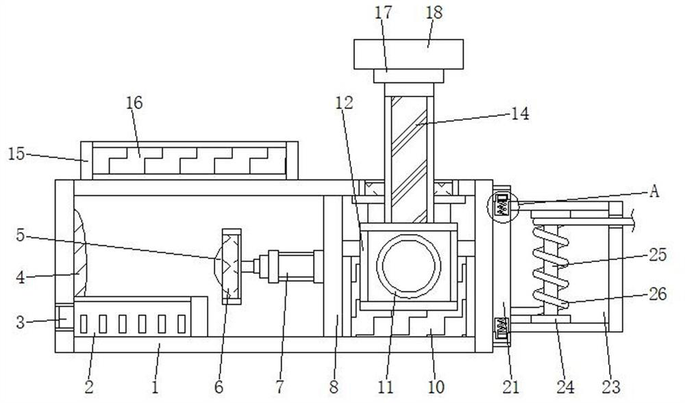
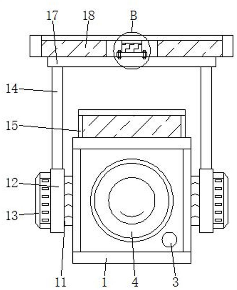
[0028] see Figure 1-5 , the present invention provides a technical solution: an electronic monitoring device capable of laser ranging and having a hidden function, including a housing 1, a lens 4 and a mounting plate 6, a laser sensor 2 is installed inside the housing 1, and the laser sensor 2 A laser generator 3 is arranged on the left side, a camera 5 is arranged on the right side of the eyeglass 4, and the eyeglass 4 is positioned above the laser sensor 2,...


PUM


Abstract

The invention belongs to the technical field of electronic monitoring equipment, and particularly relates to electronic monitoring equipment with a laser ranging function and a hiding function. The electronic monitoring equipment comprises a shell, a lens and a mounting plate, the shell is internally provided with a laser sensor, the left side of the laser sensor is provided with a laser generator, and the right side of the lens is provided with a camera and the lens is mounted above the laser sensor; an electric push rod is connected to the right side of the mounting plate, the mounting plate is located on the right side of the camera, a partition plate is fixed to the right side of the electric push rod, a heat dissipation mechanism is installed on the right side of the partition plate, a power source is fixed to the lower portion of the heat dissipation mechanism, and a rotating disc is connected to the front end of the shell. According to the electronic monitoring equipment with the laser ranging function and the hiding function, the focal length can be conveniently adjusted, shooting can be carried out at different distances, the heat dissipation performance is high, the interior is not prone to overheating, the structure is flexible, angle adjustment can be carried out according to conditions, the shooting range is large, and wires can be hidden.

Description

technical field [0001] The invention relates to the technical field of electronic monitoring equipment, in particular to an electronic monitoring equipment capable of laser distance measurement and with hidden functions. Background technique [0002] The monitoring system is mainly composed of two parts: front-end equipment and back-end equipment. Perform their duties and establish corresponding links with various equipment in the central control system through wired, wireless or optical fiber transmission media. Electronic monitoring equipment refers to the front-end equipment in the monitoring system. [0003] The traditional electronic monitoring equipment is not easy to adjust the focus distance, which makes it difficult to shoot at different distances. The heat dissipation performance is poor, the interior is easy to overheat, the structure is not flexible, and the angle cannot be adjusted according to the situation. It is impossible to hide the wires, it needs to be e...

Claims


Application Information

Patent Timeline
Patent Type & Authority Applications(China)
IPC IPC(8): H04N5/225H04N5/232B65H54/28G03B17/55
CPCG03B17/55B65H54/2851H04N23/51H04N23/55H04N23/671
Inventor 沈忠美
Owner 杭州羿涛通信技术有限公司
Why Eureka
Try Eureka