
Super-resolution infrared imaging system and image stabilization method and device thereof

An infrared imaging system and super-resolution technology, applied in the field of infrared thermal imaging, can solve problems such as image blurring, achieve the effects of ensuring coincidence, avoiding image blurring, and realizing displacement compensation

Pending Publication Date: 2021-12-10
LUOYANG INST OF ELECTRO OPTICAL EQUIP OF AVIC
View PDF0 Cites 0 Cited by
  • Summary
  • Abstract
  • Description
  • Claims
  • Application Information

AI Technical Summary

Problems solved by technology

[0005] The purpose of this application is to provide an image stabilization method for a super-resolution infrared imaging system to solve the problem of image blurring caused by vibration in existing infrared imaging; at the same time, it also proposes an image stabilization device for a super-resolution infrared imaging system , to solve the problem of image blurring caused by vibration in existing infrared imaging; at the same time, a super-resolution infrared imaging system is proposed to solve the problem of image blurring caused by vibration in existing infrared imaging

Method used


Image

  • Super-resolution infrared imaging system and image stabilization method and device thereof
  • Super-resolution infrared imaging system and image stabilization method and device thereof
  • Super-resolution infrared imaging system and image stabilization method and device thereof

Examples


Embodiment Construction

[0045] Embodiment of super-resolution infrared imaging system:

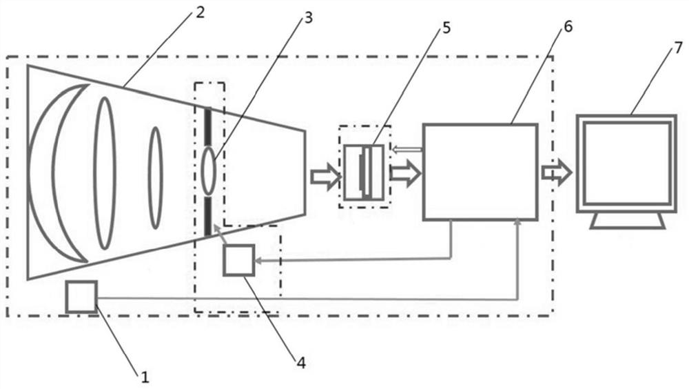
[0046] Super-resolution infrared imaging systems such as figure 1 As shown, it includes an inertial sensor 1, an imaging lens group 2, a scanning mirror 3, a micro-sweeper 4, an infrared sensor 5, a control device 6, and a display 7. The infrared imaging system is mounted on a movable platform and realized by moving the platform. Infrared imaging.

[0047] The imaging lens group 2 is used to realize the imaging of the object to be imaged; the micro-sweeper 4 is connected to the control device 6, and is used to receive the control amount of the set timing output by the control device 6 to drive the scanning mirror 3 to move;

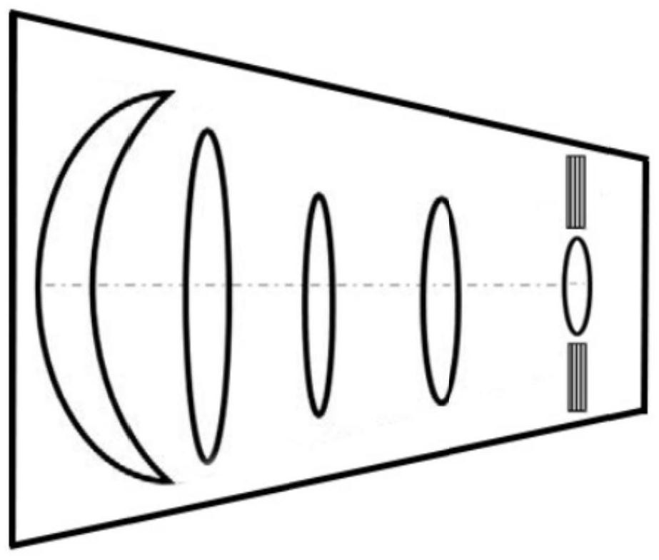
[0048] The scanning mirror 3 is a transmissive high-speed scanning mirror with an accuracy of up to 0.1 μm and a bandwidth of up to 1 KHz. In order to make the lens size and weight of the scanning mirror 3 small, such as figure 2 As shown, its position is set in the optical path of the im...


PUM


Abstract

The invention relates to a super-resolution infrared imaging system and an image stabilization method and device thereof, and belongs to the technical field of infrared thermal imaging. The image stabilization method comprises the following steps: acquiring the vibration quantity of a platform at the current moment and the required displacement of a scanning mirror at the next moment; obtaining the offset of the imaging position and the photosensitive position at the next moment according to the vibration quantity of the platform at the current moment; obtaining the compensation amount of the scanning mirror at the next moment according to the offset; determining the actual displacement of the scanning mirror at the next moment according to the compensation amount and the required displacement; and obtaining the control quantity of the driving device according to the actual displacement, so that the driving device is controlled by the control quantity. Displacement compensation of the scanning mirror is achieved through the platform vibration quantity at the current moment, it is guaranteed that the imaging position and the light sensing position coincide, and the problem of image blurring caused by vibration is avoided.

Description

technical field [0001] The invention relates to a super-resolution infrared imaging system and its image stabilization method and device, belonging to the technical field of infrared thermal imaging. Background technique [0002] Infrared imaging technology is a technology that converts invisible infrared radiation energy into visible images. It uses infrared detectors sensitive to infrared bands to collect the infrared radiation energy distribution of objects, and then recovers the images of objects through appropriate algorithms. . [0003] Infrared imaging technology is limited by the technical development level of infrared detectors. Although large-scale infrared focal plane detectors can be made at present, it is difficult to prepare infrared crystal materials with large size and good uniformity, which is difficult to meet the requirements of use, and infrared The manufacturing process level of focal plane detectors is not perfect, which leads to not only high cost of ...

Claims


Application Information

Patent Timeline
Patent Type & Authority Applications(China)
IPC IPC(8): H04N5/33H04N5/217G02B26/10
CPCH04N5/33G02B26/10H04N23/81
Inventor 范大勇黄涛
Owner LUOYANG INST OF ELECTRO OPTICAL EQUIP OF AVIC
Learn More