Earphone charging box

A charging box and earphone technology, applied in different directions of battery charging, earpiece/earphone accessories, rechargeable batteries/devices, etc., can solve the problem that the light transmission pattern of the earphone charging box is difficult to replace, and achieve the effect of easy replacement

Pending Publication Date: 2021-12-10
广东鸣洋智能科技有限公司
View PDF0 Cites 2 Cited by
  • Summary
  • Abstract
  • Description
  • Claims
  • Application Information

AI Technical Summary

Problems solved by technology

[0003] One of the purposes of the embodiments of the present application is to provide an earphone charging box, which aims to solve the technical problem in the prior art that the light-transmitting pattern of the earphone charging box is difficult to replace

Method used


Image

  • Earphone charging box
  • Earphone charging box
  • Earphone charging box

Examples


Embodiment 1

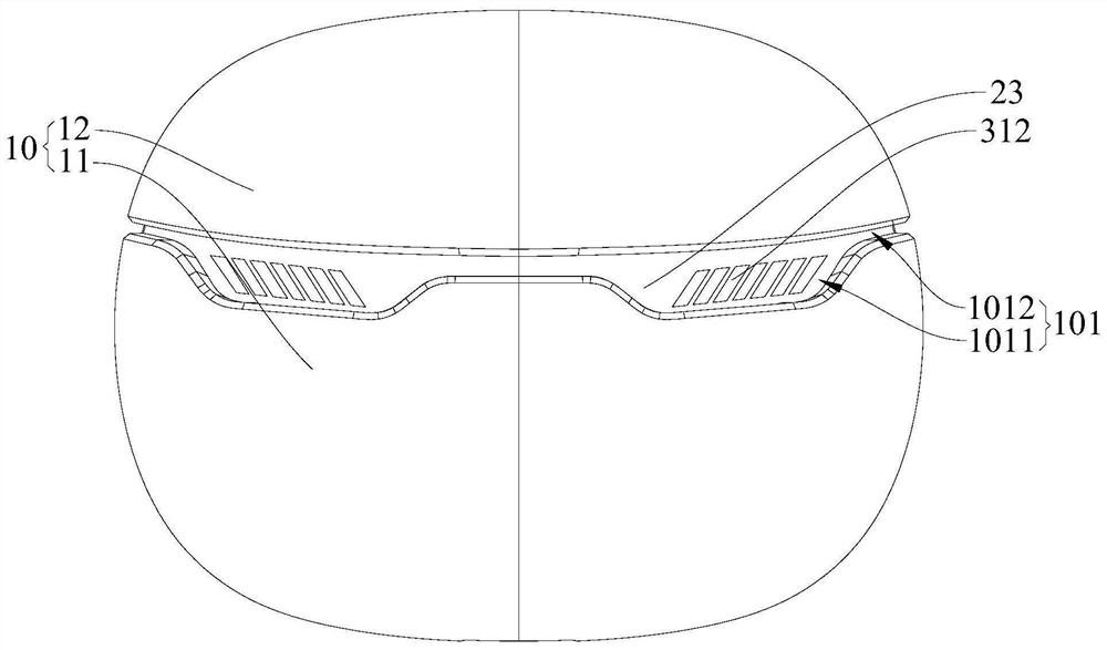
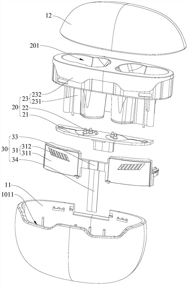
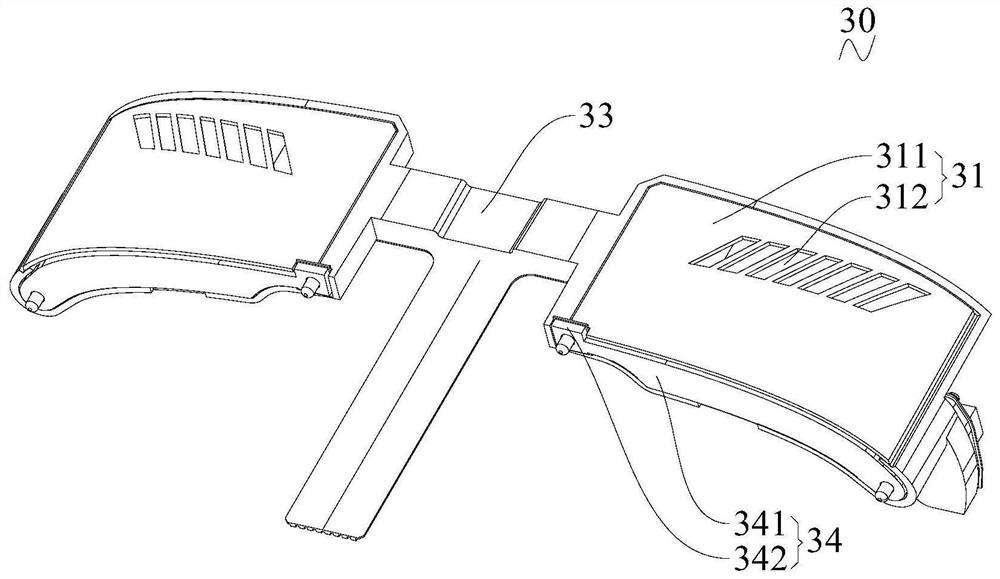
[0040] Please also refer to Figure 1 to Figure 6 , the earphone charging box provided in the embodiment of the present application includes a housing 10 , a charging component 20 and an identification component 30 . The shell 10 is penetrated with an exposed groove 101 . It can be understood that the exposed groove 101 runs through the side wall of the shell 10 and communicates with the inside and the outside of the shell 10 respectively. The charging assembly 20 is accommodated in the housing 10 , wherein, when charging, the earphone is accommodated in the housing 10 , and the charging assembly 20 charges the earphone accommodated in the housing 10 . The identification assembly 30 includes an identification sheet 31 and an indicator light 32, both of which are accommodated in the casing 10; the indicator light 32 is electrically connected to the charging assembly 20, and the identification sheet 31 includes a substrate 311 and a light-transmitting pattern 312; The sheet 311...

Embodiment 2

[0074] see Figure 8 , this embodiment is substantially the same as the first embodiment, the only difference is that the transparent pattern 312 is different.

[0075] The rest of this embodiment is the same as that of Embodiment 1, and the features not explained in this embodiment are explained in Embodiment 1, and will not be repeated here.

Embodiment 3

[0077] see Figure 9 , this embodiment is substantially the same as the first embodiment, the only difference is that the transparent pattern 312 is different.

[0078] The rest of this embodiment is the same as that of Embodiment 1, and the features not explained in this embodiment are explained in Embodiment 1, and will not be repeated here.


PUM


Abstract

The invention provides an earphone charging box, and the earphone charging box comprises: a shell which is provided with an exposed groove in a penetrating manner; a charging assembly which is accommodated in the shell; and an identification assembly which comprises an identification piece and an indicator lamp electrically connected to the charging assembly, wherein the identification piece comprises a substrate detachably installed in the shell and a light-transmitting pattern arranged on the substrate, the substrate faces the exposed groove, the exposed groove is arranged outside the light-transmitting pattern in a surrounding mode, and the light-transmitting pattern and the exposed groove are used for allowing light emitted by the indicator lamp to penetrate in sequence. By adopting the technical scheme, the light-transmitting pattern is arranged on the substrate, so that the shell does not need to be hollowed out, and therefore, when the light-transmitting pattern of the earphone charging box needs to be replaced, only identification sheets with different light-transmitting patterns need to be replaced, and the shell of the whole earphone charging box does not need to be replaced; therefore, the light-transmitting pattern of the earphone charging box is easy to replace, and the pursuit of a user for various identification effects can be met.

Description

technical field [0001] The present application belongs to the technical field of earphone charging boxes, and more specifically relates to an earphone charging box. Background technique [0002] The shell of earphone charging boxes on the market is generally hollowed out to form a light-transmitting pattern. When the indicator light in the shell is on, the light emitted by the indicator light passes through the light-transmitting pattern, thus playing a role of identification. However, since the light-transmitting pattern is directly hollowed out from the shell, it is difficult to replace the light-transmitting pattern of the earphone charging box after it is formed, so that the enrichment of the light-transmitting pattern cannot be realized, and the user's pursuit of various identification effects cannot be satisfied. Contents of the invention [0003] One of the purposes of the embodiments of the present application is to provide an earphone charging box, which aims to s...

Claims


Application Information

Patent Timeline
IPC IPC(8): H04R1/10H02J7/00
CPCH04R1/1025H02J7/0045H02J7/0047
Inventor 何长毛林力杨勇宋梦帆
Owner 广东鸣洋智能科技有限公司
Why Eureka
Try Eureka