Cabinet base damping device and cabinet

A shock absorber and cabinet technology, which is applied in the direction of springs/shock absorbers, casings/cabinets/drawer parts, mechanical equipment, etc., can solve the problems of mutual collision of electrical equipment and equipment damage, and reduce damage Effect

Pending Publication Date: 2021-12-10
安徽海兴科技设备有限公司
View PDF8 Cites 1 Cited by
  • Summary
  • Abstract
  • Description
  • Claims
  • Application Information

AI Technical Summary

Problems solved by technology

[0002] A cabinet is a free-standing or self-supporting enclosure used to accommodate electrical or electronic equipment. The cabinet is generally equipped with doors, removable or non-removable side panels and back panels. The cabinet is an integral part of electrical equipment. The carrier of the control equipment is generally made of cold-rolled steel plate or alloy, which can provide protection against storage equipment such as waterproof, dustproof, and electromagnetic interference; the existing cabinets are often simply reinforced from the material in terms of shock absorption , when the cabinet shakes violently due to external factors, the electrical equipment in the cabinet will collide with each other, resulting in damage to the equipment. For this reason, we have introduced a shock absorber for the cabinet base and a cabinet

Method used


Image

  • Cabinet base damping device and cabinet
  • Cabinet base damping device and cabinet
  • Cabinet base damping device and cabinet

Examples


Embodiment Construction

[0022] The following will clearly and completely describe the technical solutions in the embodiments of the present invention with reference to the accompanying drawings in the embodiments of the present invention. Obviously, the described embodiments are only some, not all, embodiments of the present invention. Based on the embodiments of the present invention, all other embodiments obtained by persons of ordinary skill in the art without making creative efforts belong to the protection scope of the present invention.

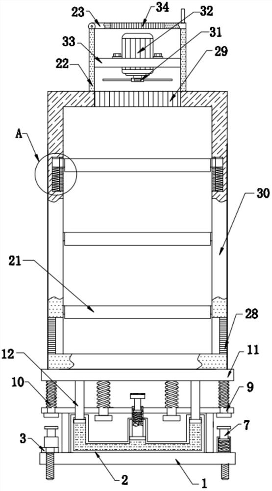
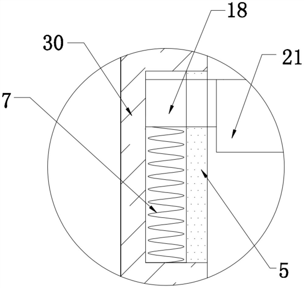
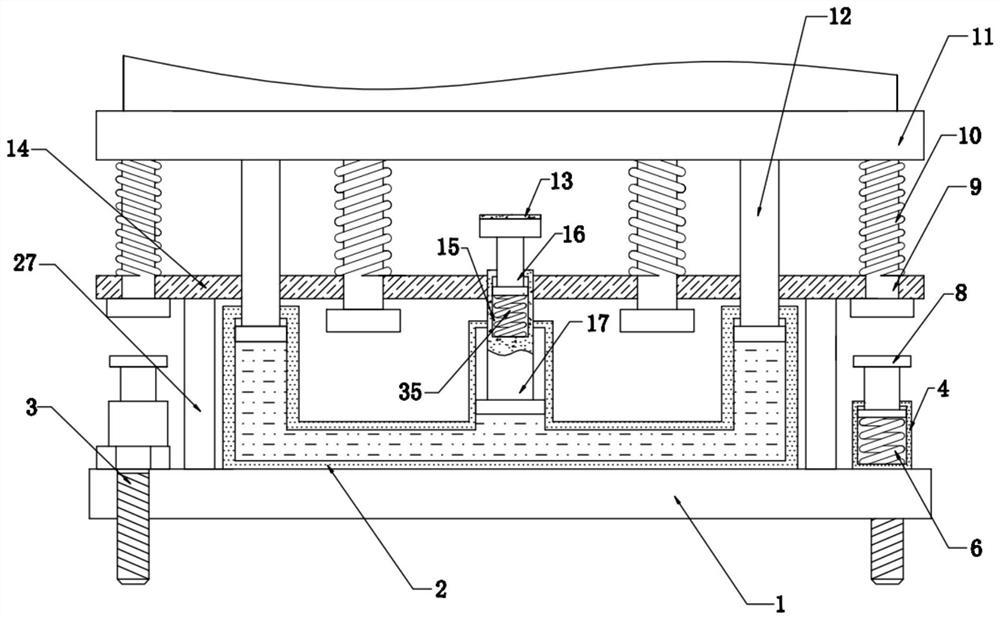
[0023] see Figure 1-6 , the present invention provides a technical solution: a shock absorbing device for a cabinet base, including a base 1, the left and right sides of the upper end of the base 1 are respectively fixedly connected with support plates 27, and the upper ends of the two sets of support plates 27 are respectively fixedly connected to the connecting plate 14 the left and right sides of the lower end, the front and rear sides of the upper end of ...


PUM


Abstract

The invention discloses a cabinet base damping device and a cabinet. The device comprises a base, supporting plates are fixedly connected to the left side and the right side of the upper end of the base correspondingly, the upper ends of the two supporting plates are fixedly connected to the left side and the right side of the lower end of a connecting plate correspondingly, and hydraulic pipes are fixedly connected to the front side and the rear side of the upper end of the base correspondingly; and first T-shaped rods are movably connected into the left sides and the right sides of the upper ends of the two hydraulic pipes correspondingly, the lower ends of two third T-shaped rods penetrate through a connecting plate and are movably connected into the connecting plate, the two third T-shaped rods are sleeved with second springs, and a heat dissipation mechanism is fixedly connected to the upper end of the cabinet. When the cabinet is vibrated, a mounting plate located in the cabinet moves up and down along T-shaped grooves through T-shaped blocks on the two sides of the mounting plate, meanwhile, the two first T-shaped rods located in the middle of the lower end of a bottom plate continuously move downwards and extrude hydraulic oil in the hydraulic pipes, and damage to the cabinet and electrical equipment in the cabinet when the vibration strength is too large is reduced.

Description

technical field [0001] The invention relates to the technical field of cabinets, in particular to a shock absorbing device for a cabinet base and a cabinet. Background technique [0002] A cabinet is a free-standing or self-supporting enclosure used to accommodate electrical or electronic equipment. The cabinet is generally equipped with doors, removable or non-removable side panels and back panels. The cabinet is an integral part of electrical equipment. The carrier of the control equipment is generally made of cold-rolled steel plate or alloy, which can provide protection against storage equipment such as waterproof, dustproof, and electromagnetic interference; the existing cabinets are often simply reinforced from the material in terms of shock absorption , When the cabinet shakes violently due to external factors, the electrical equipment in the cabinet will collide with each other, resulting in damage to the equipment. For this reason, we have introduced a shock absorbi...

Claims


Application Information

Patent Timeline
Patent Type & Authority Applications(China)
IPC IPC(8): H05K5/02F16F15/023F16F15/08
CPCH05K5/02H05K5/0217F16F15/085F16F15/023
Inventor 吴中仁
Owner 安徽海兴科技设备有限公司
Why Eureka
Try Eureka