Metal pipe fitting bending equipment

A technology for metal pipe fittings and equipment, applied in the field of metal pipe bending equipment, can solve the problems of displacement, difficult to adjust the bending angle, affecting the shape and angle of the bending pipe, and achieve the effect of simple equipment structure

Inactive Publication Date: 2021-12-14
杭州中知华谷科技有限公司
View PDF0 Cites 0 Cited by
  • Summary
  • Abstract
  • Description
  • Claims
  • Application Information

AI Technical Summary

Problems solved by technology

[0002] Existing metal pipe fittings have many disadvantages in the bending process. The first disadvantage is that it is difficult to adjust when bending pipes with different radian values, and it is also difficult to adjust the bending process for pipes with different diameters. It is difficult to adjust the corresponding bending angle, and because the pipes of different diameters cannot restrict the pipes on both sides when they pass through the existing metal pipe bending equipment, it is easy to cause slight bending during the bending process of the existing pipes. The displacement affects the shape and angle of the bending pipe, and the structure for bending the pipe in the existing equipment cannot be adjusted at the same time during the adjustment process, and the distance between the bending structure and the inside of the equipment cannot be adjusted uniformly. It needs to be individually adjusted one by one to be able to realize the telescopic adjustment of the bending structure

Method used


Image

  • Metal pipe fitting bending equipment
  • Metal pipe fitting bending equipment
  • Metal pipe fitting bending equipment

Examples


Embodiment Construction

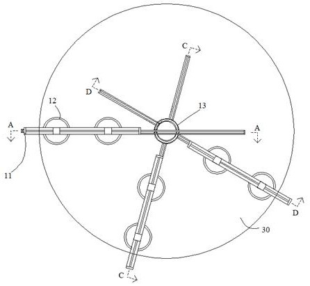
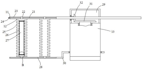
[0019] Such as Figure 1-Figure 5 As shown, the present invention is described in detail. For the convenience of description, the orientations mentioned below are now stipulated as follows: figure 1 The up, down, left, right, front and back directions of the projection relationship itself are consistent. A metal pipe bending equipment of the present invention includes a matching box 13, and the outer surface of the matching box 13 is rotated. An outer bracket 30 is arranged inside the outer bracket 30. There are several bottom chute 28, the opening of the bottom chute 28 is provided, and three boxes 11 are provided for sliding in the matching box 13, and there is a gap between the box 11 and the outer support 30 for pipe material The placing device placed therebetween, the said matching box body 13 is provided with a driving device that simultaneously makes the said box body 11 extend and retract into the said matching box body 13 .

[0020] Beneficially, wherein, the placeme...


PUM


Abstract

The invention discloses metal pipe fitting bending equipment which comprises a matching box body, an outer side support is rotationally arranged on the outer surface of the matching box body, a plurality of bottom sliding grooves are formed in the outer side support, the bottom sliding grooves are opened, three box bodies are arranged in the matching box body in a sliding mode, a placing device used for placing pipes between the box body and the outer side support is arranged between the box body and the outer side support, and a driving device enabling the box body to stretch out of and retract into the matching box body at the same time is arranged in the matching box body. According to the equipment, the distance between bending rollers can be changed, and the size and range between the rollers are adjusted according to a non-passing position.

Description

technical field [0001] The invention relates to the technical field of metal pipe bending equipment, in particular to a metal pipe bending equipment. Background technique [0002] Existing metal pipe fittings have many disadvantages in the bending process. The first disadvantage is that it is difficult to adjust when bending pipes with different radian values, and it is also difficult to adjust the bending process for pipes with different diameters. It is difficult to adjust the corresponding bending angle, and because the pipes of different diameters cannot restrict the pipes on both sides when they pass through the existing metal pipe bending equipment, it is easy to cause slight bending during the bending process of the existing pipes. The displacement affects the shape and angle of the bending pipe, and the structure for bending the pipe in the existing equipment cannot be adjusted at the same time during the adjustment process, and the distance between the bending struc...

Claims


Application Information

Patent Timeline
Patent Type & Authority Applications(China)
IPC IPC(8): B21D7/16B21D7/08
CPCB21D7/16B21D7/08
Inventor 唐花女
Owner 杭州中知华谷科技有限公司
Why Eureka
Try Eureka