
Diaphragm compressor gas side leakage guide hole device

A technology of diaphragm compressors and guide holes, which is applied in mechanical equipment, machines/engines, liquid variable capacity machines, etc. It can solve problems such as production stop loss, leaking pressure instruments, and labor hours loss, and achieve the effect of extending the maintenance cycle

Pending Publication Date: 2021-12-14
HOWDEN HUA ENG CO LTD
View PDF0 Cites 0 Cited by
  • Summary
  • Abstract
  • Description
  • Claims
  • Application Information

AI Technical Summary

Problems solved by technology

[0003] The defect of the existing technology is that when the compressor runs for a long time or the operating condition is unstable, the high-temperature and high-pressure gas (especially small molecule gas, such as hydrogen) in the membrane head can easily penetrate the gas disc sealing ring , Occasional gas leakage occurs, causing the pressure instrument for leakage detection to alarm and shut down
When the membrane head of the compressor was disassembled and inspected, it was found that the diaphragm and the sealing ring were not obviously damaged, but the downtime for maintenance caused a lot of production shutdown losses, and the disassembly of the membrane head caused a lot of labor hours.

Method used


Image

  • Diaphragm compressor gas side leakage guide hole device
  • Diaphragm compressor gas side leakage guide hole device
  • Diaphragm compressor gas side leakage guide hole device

Examples


Embodiment 1

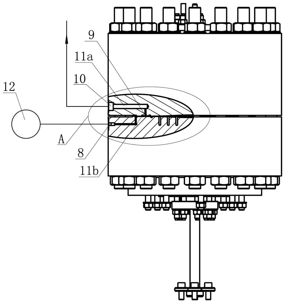
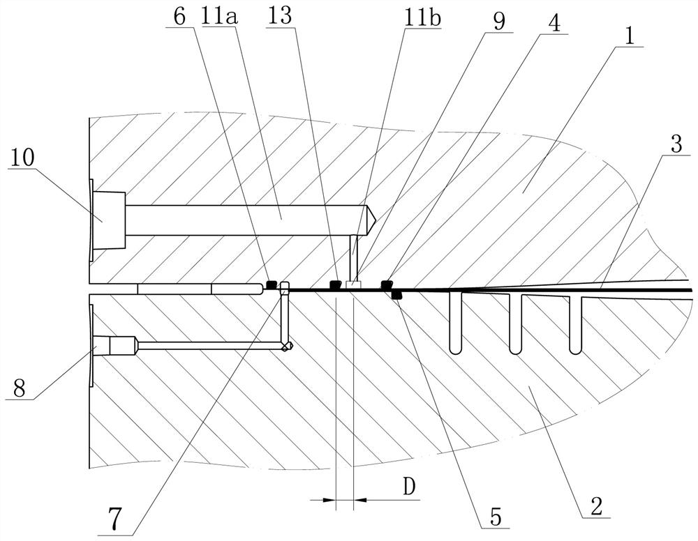
[0018] The diaphragm compressor gas side leakage guide hole device described in this embodiment, such as figure 1 with image 3 As shown, the air pan 1 and the oil pan 2 of the diaphragm compressor are included. A diaphragm 3 is provided between the air pan 1 and the oil pan 2. The air pan 1 and the diaphragm 3 are connected to form a closed air cavity. The oil pan 2 and the membrane The plates 3 are connected to form a closed oil chamber, an air disc sealing ring 4 is provided on the contact surface between the air disc 1 and the diaphragm 3, and an oil pan sealing ring 5 is provided on the contact surface between the oil pan 2 and the diaphragm 3 . On one side of the air pan 1, there is an air pan leakage converging groove 9, and the air pan leakage converging groove 9 communicates with the air pan leakage interface 10 through a guide hole. The guide hole is divided into a radial guide hole 11a and an axial guide hole 11b, and the radial guide hole 11a The two ends of the ...

Embodiment 2

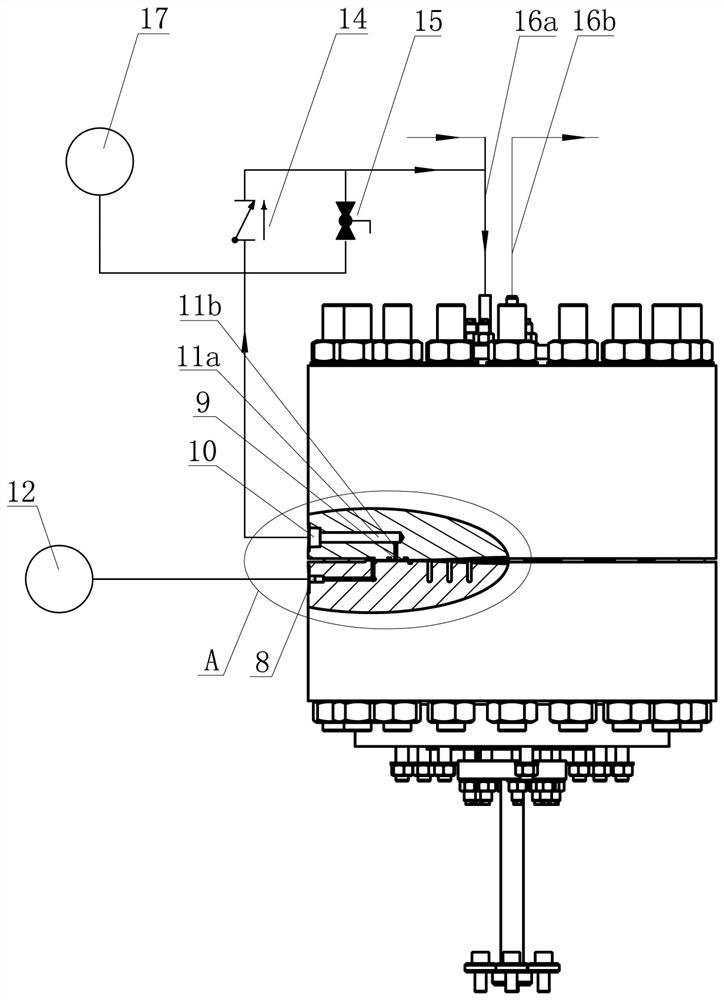
[0024] The gas-side leakage guide hole device of the diaphragm compressor described in this embodiment is an improvement to Embodiment 1 on the basis of Embodiment 1, such as figure 2 with image 3 As shown, the gas pan leakage interface 10 of the device is connected with a pressure gauge 17, and according to the reading of the pressure gauge 17, it can be judged whether there is leakage on the gas pan side. The air disc leakage interface 10 is connected to the input port of the one-way valve 14, and the output port of the one-way valve 14 is connected to the intake line 16a of the diaphragm compressor, and the diaphragm compressor also includes the exhaust line 16b of the diaphragm compressor. When the pressure of the leaked gas at the side of the air disc is higher than the gas pressure of the diaphragm compressor intake line 16a, the leaked gas will return to the diaphragm compressor intake line 16a.

[0025] Specifically, the gas disc leakage port 10 is also connected to...


PUM


Abstract

The invention discloses a diaphragm compressor gas side leakage guide hole device. The device comprises a gas disc and an oil disc of a diaphragm compressor, a diaphragm and a diaphragm head leakage gathering groove are arranged between the gas disc and the oil disc, a gas disc sealing ring is arranged on the contact face between the gas disc and the diaphragm, a gas disc leakage gathering groove is formed in one side of the gas disc, and the gas disc leakage gathering groove communicates with a gas disc leakage connector through guide holes. By arranging the gas disc leakage gathering groove and the guide holes, when the gas disc sealing ring generates leakage, pressure is directly released to the gas disc leakage connector through the gas disc leakage gathering groove and the guide holes, the position can be directly discharged to a safety position or returned to a gas inlet pipeline of the compressor, leaked gas is prevented from going to a diaphragm head detection connector, and therefore the influence of false alarm and shutdown generated by accidental leakage of the gas disc sealing ring on production is avoided, and the maintenance period of a diaphragm head of the diaphragm compressor is greatly prolonged.

Description

technical field [0001] The invention belongs to the technical field of diaphragm compressor equipment, and in particular relates to a gas side leakage guide hole device of a diaphragm compressor. Background technique [0002] Diaphragm compressors on the existing market generally adopt the method of 3 rings and 1 groove for diaphragm head seal, that is, 1 gas pan seal ring, 1 oil pan seal ring, 1 outer seal ring and 1 leakage converging groove. When any one of the gas disc sealing ring, oil pan sealing ring or oil-gas side diaphragm is damaged, the pressurized gas or pressurized hydraulic oil will leak, which will be collected at the detection port of the membrane head through the leakage converging groove, and the pressure will The instrument detects leakage faults, alarms or emergency shutdowns in time. [0003] The defect of the existing technology is that when the compressor runs for a long time or the operating condition is unstable, the high-temperature and high-press...

Claims


Application Information

Patent Timeline
IPC IPC(8): F04B45/04F04B49/10
CPCF04B45/04F04B49/10
Inventor 梁向阳孙宇平夏均贵孙晓红
Owner HOWDEN HUA ENG CO LTD
Features
  • Generate Ideas
  • Intellectual Property
  • Life Sciences
  • Materials
  • Tech Scout
  • Unparalleled Data Quality
  • Higher Quality Content
  • 60% Fewer Hallucinations
Learn More