A displacement control hydraulic valve

A displacement control and hydraulic valve technology, applied in the field of hydraulic control valves, can solve the problems of many action control links and equipment failures, and achieve the effect of reducing control links, smooth oil circuit, and improving stability and reliability.

Active Publication Date: 2022-05-03
ANHUI JIANGHUAI AUTOMOBILE GRP CORP LTD
View PDF6 Cites 0 Cited by
  • Summary
  • Abstract
  • Description
  • Claims
  • Application Information

AI Technical Summary

Problems solved by technology

There are many action control links, and any problem in any of the three links of position sensor, PLC, and solenoid valve will cause equipment failure

Method used


Image

  • A displacement control hydraulic valve
  • A displacement control hydraulic valve
  • A displacement control hydraulic valve

Examples


Embodiment Construction

[0042] Various exemplary embodiments of the present invention will now be described in detail with reference to the accompanying drawings. It should be noted that the relative arrangements of components and steps, numerical expressions and numerical values ​​set forth in these embodiments do not limit the scope of the present invention unless specifically stated otherwise.

[0043] The following description of at least one exemplary embodiment is merely illustrative in nature and in no way taken as limiting the invention, its application or uses.

[0044] Techniques, methods and devices known to those of ordinary skill in the relevant art may not be discussed in detail, but where appropriate, such techniques, methods and devices should be considered part of the description.

[0045]In all examples shown and discussed herein, any specific values ​​should be construed as exemplary only, and not as limitations. Therefore, other instances of the exemplary embodiment may have diff...


PUM


Abstract

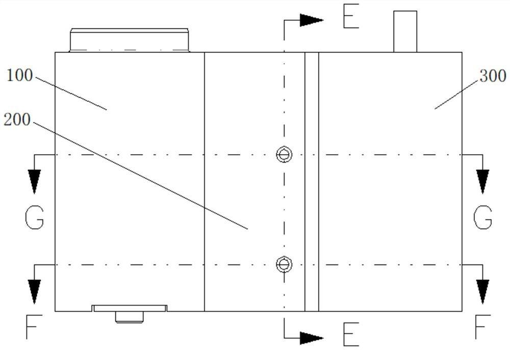
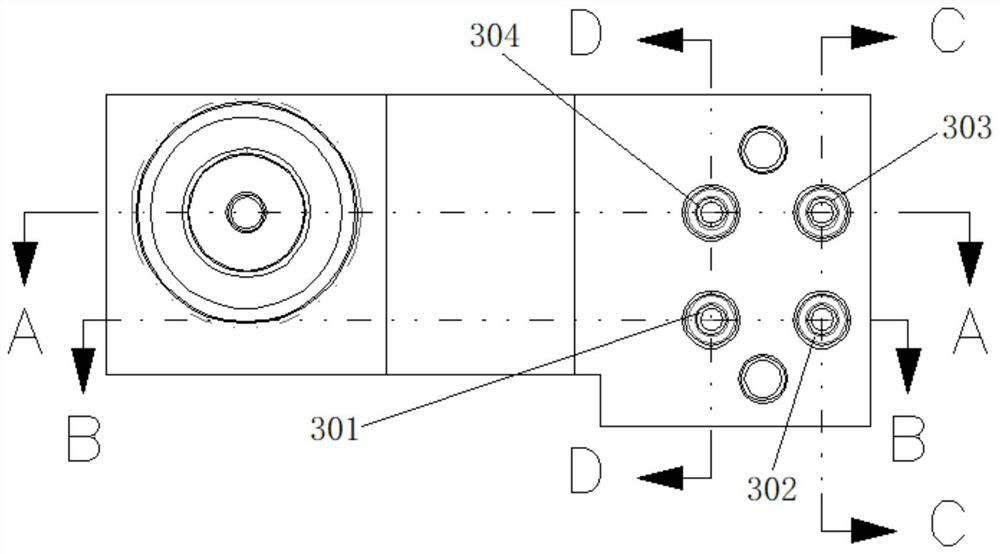
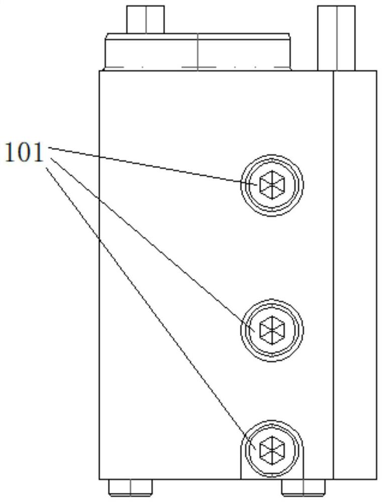
The invention discloses a displacement control hydraulic valve, which comprises an oil circuit butt joint valve block, an intermediate valve block and a displacement input valve block arranged in sequence. There is a sliding step sliding shaft inside the displacement input valve block, and the other end of the one-way valve thimble is against the side of the step sliding shaft; The ball is pushed open so that the thimble slideway communicates with the cavity, and the oil circuit is unblocked; when the check valve thimble contacts the small diameter surface of the step sliding shaft, the steel ball return spring pushes the steel ball to isolate the cavity from the thimble slideway, The oil circuit is closed, only the oil entering from the oil return port pushes away the steel ball and flows to the oil inlet under the action of the oil. The invention directly controls the opening and closing of the one-way valve through the position, realizes the direct correlation between the displacement action and the hydraulic action, and at the same time reduces the control links, improves the stability and reliability of the action interlock, and reduces the use cost.

Description

technical field [0001] The present invention relates to the technical field of hydraulic control valves, in particular to a displacement control hydraulic valve. Background technique [0002] The demand for automation in today's manufacturing industry is getting higher and higher. High automation leads to more and more complex motion monitoring mechanisms, motion interlocks, and security control strategies for equipment and facilities. [0003] One of the existing technologies is to use hydraulic oil circuit to control the action sequence, usually using sequence valve control. The control principle of the control valve is to open the sequence valve only when the oil circuit at the oil inlet of the valve has a certain pressure, so that the subsequent The oil path is connected to the oil to perform subsequent actions. The sequence control of actions can only be realized through pressure control, and the interlocking of subsequent actions with a certain action or a specific me...

Claims


Application Information

Patent Timeline
Patent Type & Authority Patents(China)
IPC IPC(8): F15B13/02
CPCF15B13/02F15B13/027F15B2013/002
Inventor 梅勇李定磊李文
Owner ANHUI JIANGHUAI AUTOMOBILE GRP CORP LTD
Why Eureka
Try Eureka