
Scanning equipment capable of achieving automatic marking

A technology of scanning equipment and automatic marking, applied in sorting and other directions, can solve the problems of increasing working hours, reducing efficiency, increasing working costs, etc., and achieving the effect of saving working hours, improving efficiency and saving working costs

Pending Publication Date: 2021-12-17
ZHEJIANG BAISHI TECH
View PDF0 Cites 0 Cited by
  • Summary
  • Abstract
  • Description
  • Claims
  • Application Information

AI Technical Summary

Problems solved by technology

[0002] In the logistics sorting process, in order to achieve efficient and fast sorting, items such as receiving boxes are used to return and receive various goods. Correspondingly, when different receiving boxes are loaded with different goods, the box Correspondingly different scannable barcodes will be pasted on the body to facilitate subsequent staff to scan and store in the warehouse. However, the receiving box is a repeatedly used item. After sorting and using in different batches, various wastes will be pasted on the box. Barcodes, due to the time-consuming and labor-intensive cleaning, these barcodes are often not cleaned by the staff, and in the next sorting use, the scanners often cannot distinguish the old and new barcodes, and then scan repeatedly on a box until they are scanned. Until the correct barcode is obtained, these waste barcodes greatly increase the working hours, lower the efficiency and increase the working cost

Method used


Image

  • Scanning equipment capable of achieving automatic marking
  • Scanning equipment capable of achieving automatic marking
  • Scanning equipment capable of achieving automatic marking

Examples


Embodiment

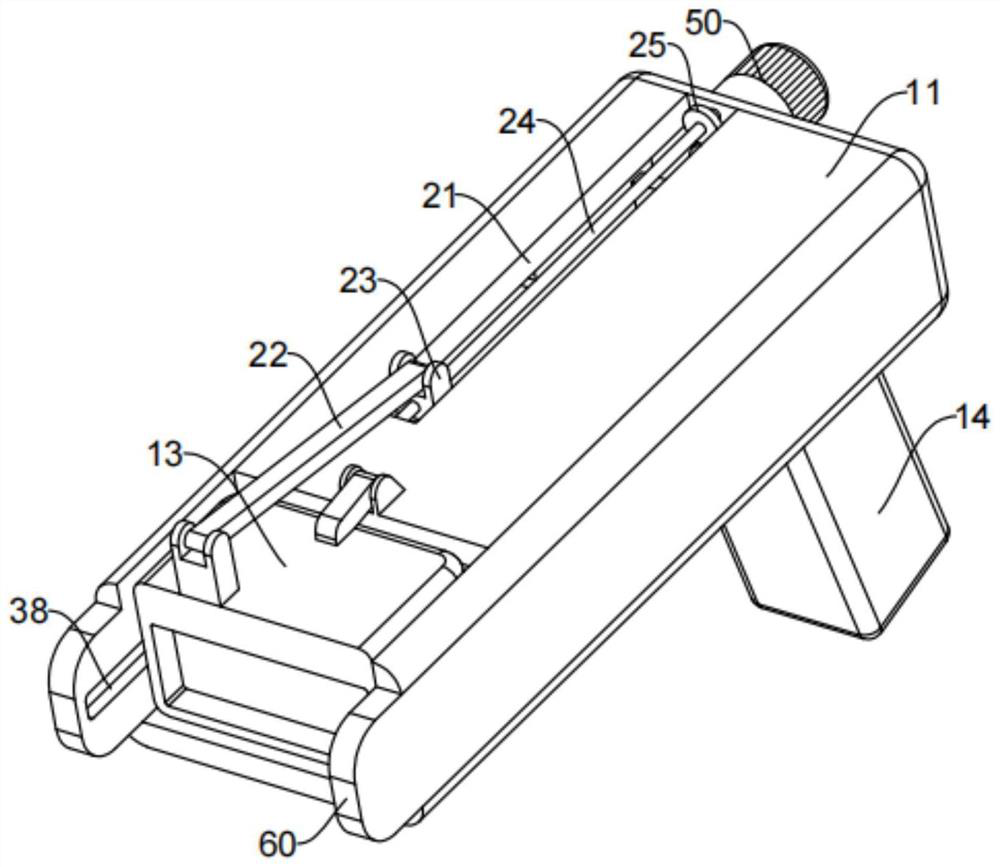
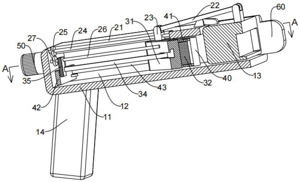
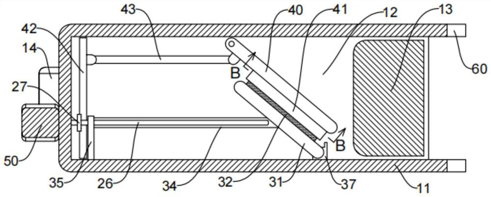
[0024] refer to Figure 1 to Figure 5 As shown, this embodiment provides a scanning device for automatic marking, which is mainly used for scanning barcodes and marking waste barcodes in logistics sorting, receiving and returning goods.

[0025] This embodiment includes a housing 11, on which a code reader 13 is hinged, and a handle 14 for holding is provided on the lower side of the housing 11, and the user holds the handle 14 to read the code The scanner 13 is aligned with the barcode to scan, and the housing 11 is provided with two positioning pieces 60 at the opening of the inner cavity 12, and the user presses the two positioning pieces 60 against both sides of the barcode for alignment. Accurate, convenient code reader 13 scans the barcode accurately and quickly.

[0026] There are generally multiple waste barcodes on a logistics receiving box. This embodiment is used to scan and mark these waste barcodes during the scanning work. At the same time, after scanning the ne...


PUM


Abstract

The invention relates to the technical field of logistics scanning equipment, in particular to scanning equipment capable of achieving automatic marking. The equipment comprises a shell, an inner cavity with the single side being opened is formed in the shell, a code reader is hinged to the shell, and a rotating mechanism for driving the code reader to rotate is arranged on the shell. A marking mechanism moving in the opening direction of the single side is arranged in the inner cavity. According to the scanning equipment capable of achieving automatic marking, the movable marking mechanism is arranged in the shell, the marking mechanism is hidden in the shell during normal scanning, scanning is performed through the code reader after the opening of the shell is aligned to a bar code, and after scanning is completed or a waste bar code is scanned, the rotating mechanism is used for driving the code reader to rotate so as to expose the marking mechanism in the shell. And meanwhile, a moving mechanism drives the marking mechanism to slide out so as to stamp a seal onto the bar code and mark the bar code so that new and old bar codes can be quickly distinguished in subsequent work, the work of repeated scanning is omitted, the working hours is shortened, the efficiency is improved, and the working cost is reduced.

Description

technical field [0001] The present invention relates to the technical field of logistics scanning equipment, in particular, to an automatic marking scanning equipment. Background technique [0002] In the logistics sorting process, in order to achieve efficient and fast sorting, items such as receiving boxes are used to return and receive various goods. Correspondingly, when different receiving boxes are loaded with different goods, the box Correspondingly different scannable barcodes will be pasted on the body to facilitate subsequent staff to scan and put them into storage. However, the receiving box is a repeatedly used item. After sorting and using in different batches, various wastes will be pasted on the box. Barcodes, due to the time-consuming and laborious cleaning, these barcodes are often not cleaned by the staff, and in the next sorting use, the scanners often cannot distinguish the old and new barcodes, and then scan repeatedly on a box until they are scanned. U...

Claims


Application Information

Patent Timeline
IPC IPC(8): B07C3/14
CPCB07C3/14
Inventor 周韶宁张砚冰张芒粒
Owner ZHEJIANG BAISHI TECH
Learn More