Image processing method for detecting objects using relative motion

a technology of relative motion and image processing, applied in the field of image processing, can solve the problems of large computational resources required by systems, ungeneric, expensive and time-consuming processes, etc., and achieve the effect of large distance d++

Active Publication Date: 2017-01-17
MAGNA ELECTRONICS INC
View PDF341 Cites 14 Cited by
  • Summary
  • Abstract
  • Description
  • Claims
  • Application Information

AI Technical Summary

Benefits of technology

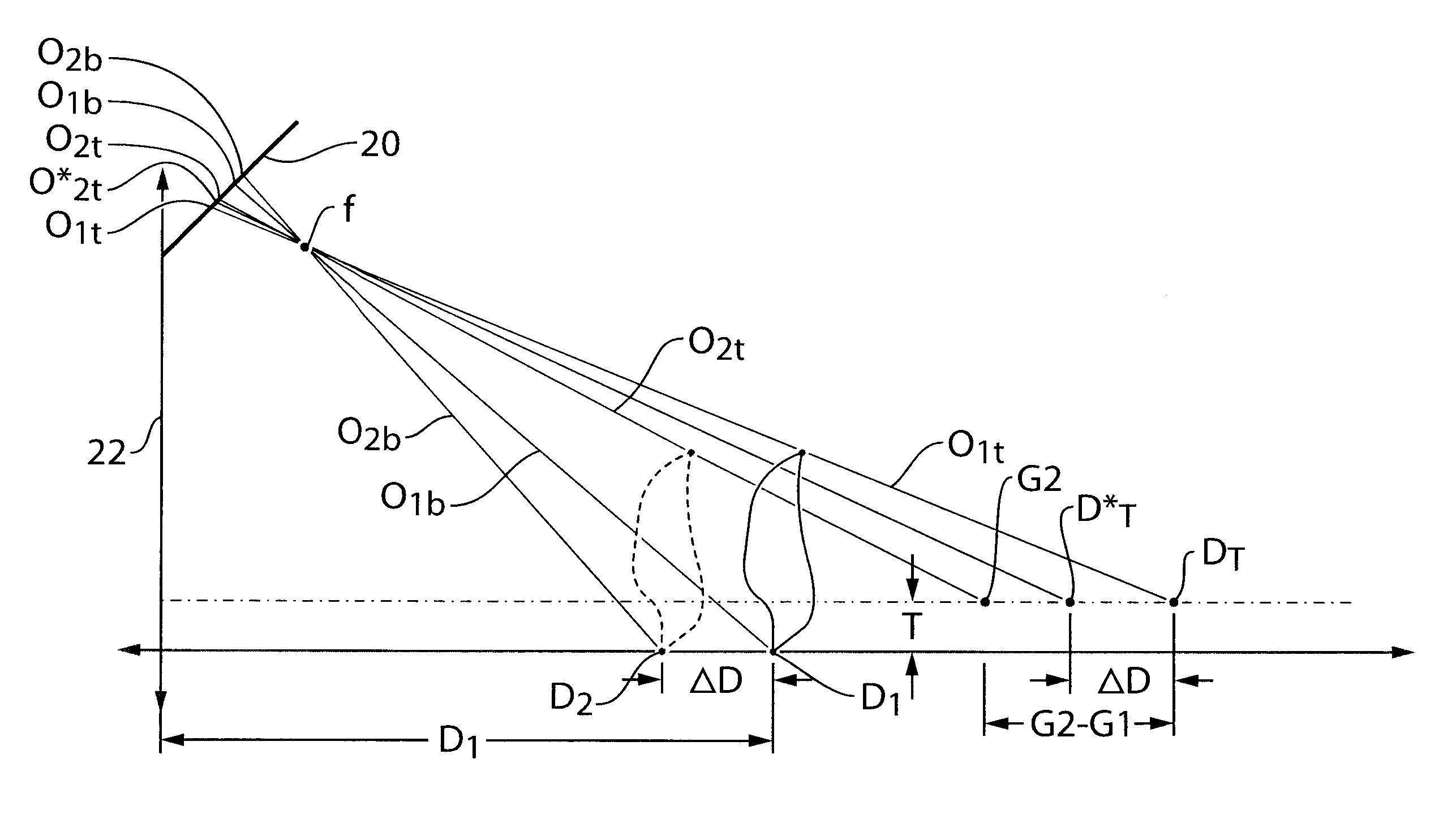
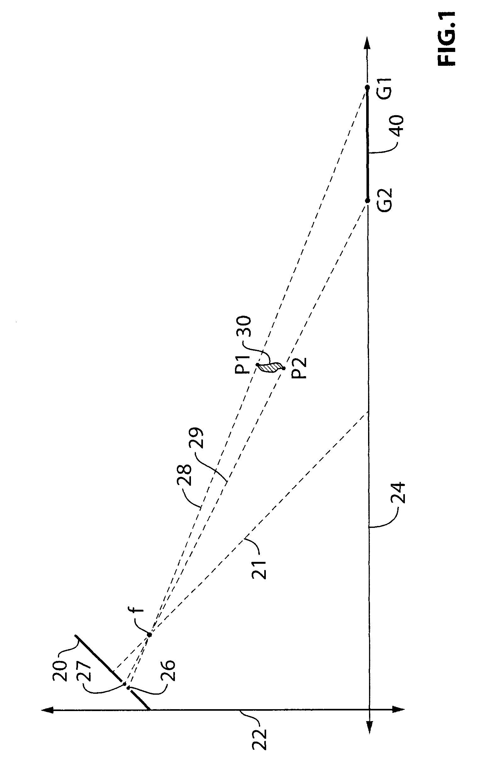
[0006]Generally speaking, the invention utilizes the principle that spaced apart physical points that in reality have a vertical dimension will move at different rates when projected to the image plane provided by the vehicular camera, whereas spaced apart physical points that in reality lie only horizontally along the ground plane will move at the same rate when projected to the image plane. Using this principle the invention is able to rapidly distinguish between three dimensional objects that could be relevant to the obstacle detection analysis and irrelevant two dimensional objects that, for example, may be pavement markings or artifacts such as shadows.
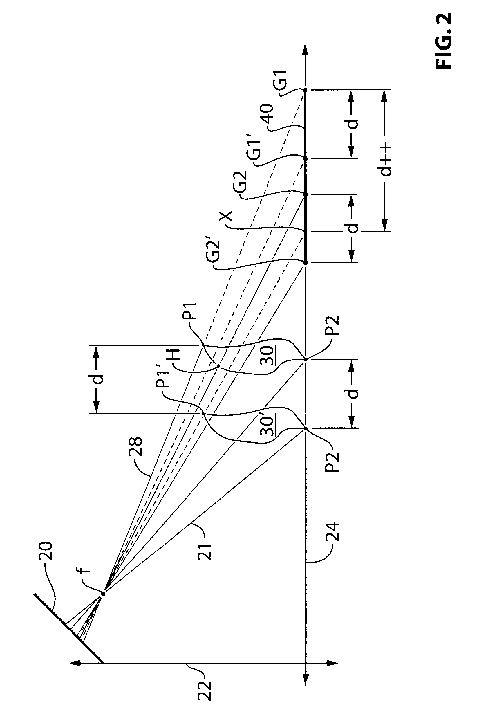
[0008]However, referring additionally to FIG. 2, if there is relative motion between the object and the image plane additional information can be garnered to be able to differentiate between a vertically oriented object and a horizontally oriented object. Consider again the horizontally oriented object 40 which lies on the ground plane. It has two opposing edge points that lie at initial positions G1, G2. (To the camera, these two points could also correspond to points P1 and H of vertical object 30.) If the horizontal object 40 moves relative to the camera by a real distance d, then the edge points will move to positions G1′, G2′. With the height and angular orientation of the camera known, it is possible to calculate the distance moved in the ground plane by the end points, i.e., the distance between G1 to G1′ and between G2 to G2. As the object is presumed to be of constant length for at least a short period of time, the distance between G1 and G1′ will be d and the distance between G2 to G2′ will also be d.
[0009]Now consider the vertical object 30. It has two opposing edge points that lie at initial positions P1, P2. The point P1, lying along ray 28, projects onto the ground plane at point G1 as previously discussed. Point P2 in this example lies along the ground plane (but it need not). Let the vertical object 30 move relative to the camera by a real distance d. The top edge point moves from position P1 to position P1′, and the bottom edge point moves from position P2 to P2′. Now calculate the distance moved in the ground plane by these end points. P1 projects onto the ground plane at point G1. Point P1′ projects onto the ground plane at point X. So, a distance calculation in the ground plane between points P1 and P1′ effectively yields a result computing the distance between G1 and X, resulting in a much larger distance d++. On the other hand, P2 and P2′ are located on the ground plane so the distance between them will be computed as d. The change d++ in the ground plane between P1 and P1′ differs considerably from the change d between P2 and P2′, thus enabling a vertical object to be distinguished from an object lying substantially along the ground plane.

Problems solved by technology

Such systems may require significant computational resources provided by expensive signal processors.
In addition, in such a system, all the objects that need to be detected have to be defined in the development stage and require extensive training for the classifiers.
Such a process is expensive and time consuming and might not be generic enough with respect to all possible different objects that might be encountered in the real world.

Method used


Image

  • Image processing method for detecting objects using relative motion
  • Image processing method for detecting objects using relative motion
  • Image processing method for detecting objects using relative motion

Examples


Embodiment Construction

[0030]For reference purposes, the following mathematical nomenclature is used in this description. A vector or a matrix is represented in bold face, while a scalar entity is represented in a regular face. The lower case is used to denote the dimensions and pixel locations in two dimensional image space. Thus, the collection of all the pixels in an image can be denoted as f and a pixel at column x and row y in the image f can be represented as f(x, y). The coordinates of a point in the three-dimensional world are represented using the upper case. A point on the ground can be represented in its vector form as X, or also as [Xw, Yw, Zw].

[0031]FIG. 3 shows a system block diagram of a preferred obstacle detection system 100. The inputs to system 100 include the image frames 102 from the vehicular camera (not explicitly shown) and vehicle CAN (controller area network) data 104 such as the instantaneous speed of the vehicle and its steering angle. In an overall system, knowledge of the veh...


PUM


Abstract

An image based obstacle detection method. A camera mounted on a vehicle provides a set of image frames while the vehicle is in motion. The image frames define an image plane having a vertical aspect and a horizontal aspect. The relevancy of an object is determined by (i) selecting first and second feature points from the object that are spaced apart vertically in a first image frame; (ii) tracking the positions of the first and second feature points over at least a second image frame; and (iii) deciding the object to be relevant if the first and second feature points move dissimilar distances in physical space, within a tolerance, and deciding the object to be irrelevant otherwise. The motion of relevant objects is then estimated to determine if any relevant object is likely to become an obstacle to the vehicle.

Description

CROSS-REFERENCE TO RELATED APPLICATIONS[0001]The present application is a 371 U.S. national phase application of PCT Application No. PCT / CA2012 / 000057 filed Jan. 20, 2012 which claims priority to U.S. Provisional Patent Application No. 61 / 478,717, filed Apr. 25, 2011.FIELD OF INVENTION[0002]The invention relates to the field of image processing, and more particularly to a method and system for discerning three-dimensional objects using relative motion between the camera and the objects, and an object detection system based on same.BACKGROUND OF INVENTION[0003]Many vehicles now incorporate one or more obstacle detection system which use cameras to provide a field of view of the roadway and surrounding environment. The obstacle detection systems process the video stream or sequence of image frames provided by the camera in an attempt to ascertain the existence of an obstacle in the path of vehicle. Obstacle detection algorithms do this by attempting identify a variety of objects local...

Claims


Application Information

Patent Timeline
Patent Type & Authority Patents(United States)
IPC IPC(8): G06K9/00G06T7/20
CPCG06K9/00805G06T7/246G06T7/248G06T2207/30261G06V20/58G06V20/64G06V20/588G06F18/22G06T7/80G06T7/74G06T7/13B60R1/00B60R2300/8093G06T5/006G06T2207/30241G06T2207/30256H04N7/183
Inventor GUPTA, NIKHIL
Owner MAGNA ELECTRONICS INC
Why Eureka
Try Eureka