Valve port conveying and detecting assembly

A technology for detecting components and valve ports, which is applied in transportation and packaging, mechanical valve testing, transportation packaging, etc., can solve problems such as difficulty in heat sealing, damage and fracture, and failure to detect transmission failures, and achieve the effect of improving production quality

Active Publication Date: 2021-12-17
WUXI HONGCHANG PRECISION MACHINERY
View PDF6 Cites 0 Cited by
  • Summary
  • Abstract
  • Description
  • Claims
  • Application Information

AI Technical Summary

Problems solved by technology

[0003] In the prior art, in order to save labor costs, the conveyor belt is usually used to convey the valve port, and a transfer device is installed at the output end of the conveyor belt to transfer the valve port to the hot pressing device for heat sealing. In this way, although automatic heat sealing can be realized, However, the accuracy is poor, and it is difficult to accurately align the valve port with the hot pressing port of the film material, which affects the production quality of the vacuum bag; in addition, the valve port and the film material are prone to various faults during the transportation process (such as the valve port detached from the conveyor belt, the film The material is damaged and broken during transmission), and the valve port transmission device in the prior art cannot detect the transmission failure, which makes it difficult to carry out heat sealing smoothly

Method used


Image

  • Valve port conveying and detecting assembly
  • Valve port conveying and detecting assembly
  • Valve port conveying and detecting assembly

Examples


Embodiment Construction

[0071] The specific implementation manners of the present invention will be further described below in conjunction with the drawings and examples. The following examples are only used to illustrate the technical solution of the present invention more clearly, but not to limit the protection scope of the present invention.

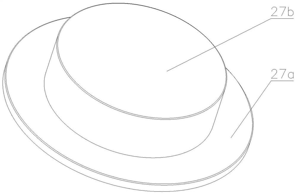
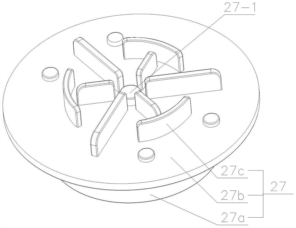
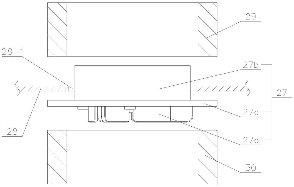
[0072] First of all, briefly describe the structure of the valve port 27 and the hot pressing and heat sealing treatment method, such as figure 1 and figure 2 As shown, the valve port 27 includes a disc-shaped chassis 27a and a boss 27b arranged on the upper surface of the chassis 27a. The axis line of the boss 27b coincides with the axis line of the chassis 27a. Valve (not shown in the figure), the bottom center of the chassis 27a is provided with a suction port 27a-1, and the circumferential direction of the suction port 27a-1 is evenly distributed with convex ribs 27c, and the outer part of the chassis 27a located on the boss 27b belongs to the hot pre...


PUM


Abstract

The invention discloses a valve port conveying and detecting assembly which comprises a rack. A conveying belt and a driving device for driving the conveying belt to rotate are arranged on the rack, a bearing table is arranged at the output end of the conveying belt, and a through hole which allows the output end of a lifting device to pass through and is located under the conveying path of a film material hot-pressing opening is formed in the bearing table. The output end is further provided with a transferring device, the transferring device is used for transferring the valve port of the output end to the position over the through hole, and the input end of the conveying belt is provided with a feeding device. A first in-place sensor is arranged over the conveying belt, and the detection end of the first in-place sensor faces the conveying belt. According to the valve port conveying and detecting assembly, the first in-place sensor and the feeding device are matched for operation, and it is guaranteed that the conveying belt can stably, orderly and smoothly convey valve ports. And at the conveying end of the conveying belt, the valve ports are transferred to the position over the through hole through the transferring device, so that the lifting device jacks the valve ports to the film material hot-pressing opening, automatic high-precision heat sealing is achieved, and the production quality of vacuum bags is improved.

Description

technical field [0001] The invention relates to the technical field of valve port delivery and detection, in particular to a valve port delivery and detection assembly. Background technique [0002] During the production process of the vacuum bag, the valve port (that is, the one-way valve) needs to be heat-sealed on the film material by hot pressing. Most of the valve port structures in the prior art are as figure 1 and figure 2 As shown, it includes the chassis and the boss set on the chassis. A one-way suction valve is arranged inside the boss. The bottom center of the chassis is provided with a suction port connected with the inner cavity of the suction cup. Ribs are evenly distributed around the suction port. The annular area outside the boss is a hot pressing area. [0003] In the prior art, in order to save labor costs, the conveyor belt is usually used to convey the valve port, and a transfer device is installed at the output end of the conveyor belt to transfer ...

Claims


Application Information

Patent Timeline
IPC IPC(8): B65B31/06B65B51/14G01M13/003
CPCB65B31/06B65B51/14G01M13/003
Inventor 王飞鸿林秋
Owner WUXI HONGCHANG PRECISION MACHINERY
Why Eureka
Try Eureka