Check patentability & draft patents in minutes with Patsnap Eureka AI!

New energy automobile mileage simulation test equipment

A new energy vehicle and simulation test technology, applied in the field of new energy vehicle mileage simulation test equipment, can solve problems such as heavy workload, long test cycle, fault inspection, and difficulty in parts replacement, and achieve accurate mileage and high degree of automation. , the effect of reducing the risk of testing

Pending Publication Date: 2021-12-17
扬州嘉之葵新能源科技有限公司
View PDF0 Cites 0 Cited by
  • Summary
  • Abstract
  • Description
  • Claims
  • Application Information

AI Technical Summary

Problems solved by technology

[0002] In recent years, under the vigorous promotion of national policies and market demand, the electric vehicle industry has developed rapidly. As a basic parameter information of electric vehicles, the driving range has always been an important basis for the majority of users to purchase electric vehicles. In order to ensure the accuracy of the driving range of the electric vehicle, after the assembly of the electric vehicle is completed, a special driving range test is required. At present, the testing method of the driving range of the electric vehicle stipulated in the national standard is based on the chassis dynamometer of the whole vehicle. , but when the mileage test is carried out on a fully assembled vehicle, if there are problems such as failure or insufficient mileage during the test, due to the limitation of the space of the vehicle and other factors, operations such as fault inspection and parts replacement will be difficult. It is extremely difficult, and the workload is large, the test period is long, and there are no sensors between the transmission components on the whole vehicle, which makes it difficult to measure the output power, efficiency and other parameters of the transmission components. It is difficult to obtain accurate test methods. electric car mileage

Method used


Image

  • New energy automobile mileage simulation test equipment
  • New energy automobile mileage simulation test equipment
  • New energy automobile mileage simulation test equipment

Examples


Embodiment Construction

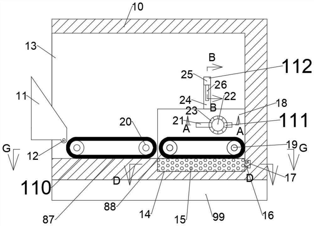
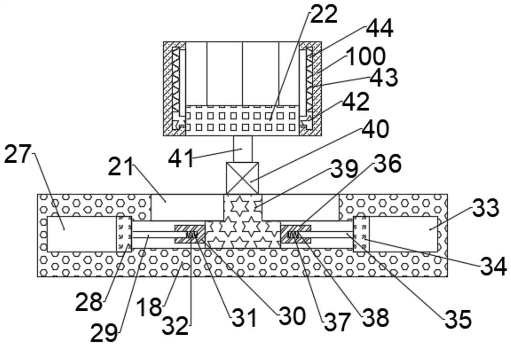
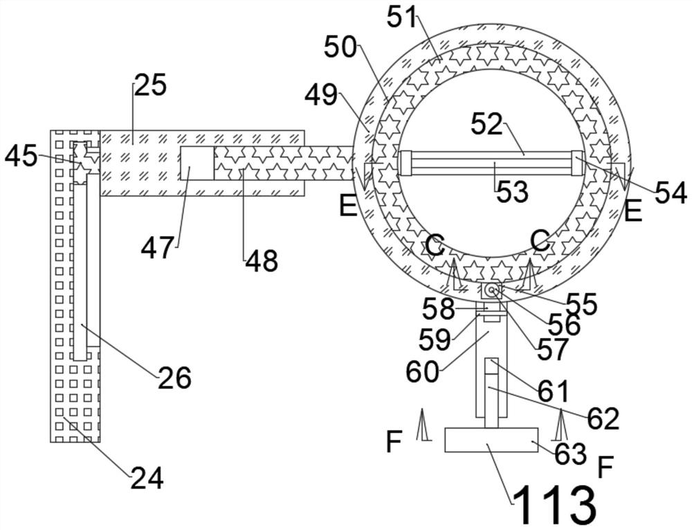
[0024] Combine below Figure 1-9 The present invention is described in detail, wherein, for the convenience of description, the orientations mentioned below are defined as follows: figure 1 The up, down, left, right, front and back directions of the projection relationship itself are the same.

[0025] combined with Figure 1-9 The new energy vehicle mileage simulation test equipment includes a slope simulation device 99, a detection box 10 is provided on the slope simulation device 99, and a detection cavity 13 with an opening to the left is provided in the detection box 10. The detection cavity 13 is provided with a first rotating cavity 14 with an opening upward, and the inner wall of the right side of the first rotating cavity 14 is provided with an annular air pressure cavity 16 with an opening facing to the left, and the upper side of the first base 15 is provided with There is a kinetic energy recovery device 111 and a steering device 112, the steering device 112 is p...


PUM


Abstract

The invention discloses new energy automobile mileage simulation test equipment which comprises a slope simulation device. A detection box is arranged on the slope simulation device, a detection cavity with a leftward opening is formed in the detection box, and a first rotating cavity with an upward opening is formed in the detection cavity. The inner wall of the right side of the first rotating cavity is provided with an annular air pressure cavity with a leftward opening. A kinetic energy recovery device and a steering device are arranged on the upper side of a first base. A driving device is arranged in the steering device, and a driving device is arranged in the detection box. In the using process, the wheels of an electric vehicle are fixed, meanwhile, power of the electric vehicle is used for generating electricity, and electric power recycling is achieved. Meanwhile, in the using process, the equipment does not need to be manually driven, and a built-in program is used to simulate actual road conditions to conduct uphill and downhill driving, steering, acceleration and braking. The equipment is high in automation degree and does not need manual driving, so that the test risk can be greatly reduced. Meanwhile, a more accurate mileage can be obtained by simulating real road conditions.

Description

technical field [0001] The invention relates to the field of new energy vehicles, in particular to a mileage simulation test device for new energy vehicles. Background technique [0002] In recent years, under the vigorous promotion of national policies and market demand, the electric vehicle industry has developed rapidly. As a basic parameter information of electric vehicles, the driving range has always been an important basis for the majority of users to purchase electric vehicles. In order to ensure the accuracy of the driving range of the electric vehicle, after the assembly of the electric vehicle is completed, a special driving range test is required. At present, the testing method of the driving range of the electric vehicle stipulated in the national standard is based on the chassis dynamometer of the whole vehicle. , but when the mileage test is carried out on a fully assembled vehicle, if there are problems such as failure or insufficient mileage during the test,...

Claims


Application Information

Patent Timeline
IPC IPC(8): G01M17/007
CPCG01M17/007
Inventor 高军
Owner 扬州嘉之葵新能源科技有限公司
Features
  • R&D
  • Intellectual Property
  • Life Sciences
  • Materials
  • Tech Scout
  • Unparalleled Data Quality
  • Higher Quality Content
  • 60% Fewer Hallucinations
Learn More