Ultrahigh-temperature air disinfection equipment
An ultra-high temperature and air technology, applied in the field of air purification, can solve the problems of low one-time disinfection rate, inability to miniaturize, and inability to use equipment in places with people
- Summary
- Abstract
- Description
- Claims
- Application Information
AI Technical Summary
Problems solved by technology
Method used
Image
Examples
Embodiment 1
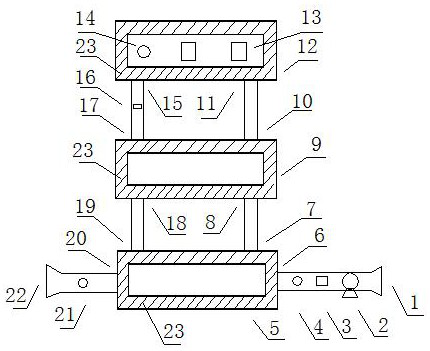
[0014] like figure 1 As shown, an ultra-high temperature air antivirus device includes an air inlet 1, a fan 2 installed behind the air inlet 1 forms an air inlet section, and the air after the air intake enters the plate heat exchanger air inlet 6 installed behind the fan 2 , flows through the inner channel of plate heat exchanger one 5 to reach the outlet of plate heat exchanger one 7, and absorbs heat in plate heat exchanger one 5 at the same time, the air is preheated and heated up, and the virus is initially heated, dried and dehydrated. The air from the plate heat exchanger air outlet 1 7 enters the plate heat exchanger air inlet 3 8, flows through the spiral plate heat exchanger 9 and reaches the plate heat exchanger air outlet 3 10, while at the spiral plate heat exchanger 9 The internal heat absorption continues to heat up. The air coming out from the air outlet 310 of the plate heat exchanger enters the high temperature box 12 from the air inlet 11 of the high tempe...
Embodiment 2
[0016] The number of electric heating modules 13 in the high temperature box 12 can be one or more, and the electric heating modules 13 are arranged at any suitable position inside the high temperature box 12 , especially a position near the air inlet 11 of the high temperature box. The electric heating module 13 in the high temperature box 12 can be heated to a temperature of more than 250 degrees Celsius, and can even be heated to a high temperature of more than 500 degrees Celsius. The virus will die instantly when encountering ultra-high temperature, so as to achieve the purpose of rapid disinfection.
[0017] [Example 2]
[0018] The flow meter 13 and the temperature sensor 14 are installed between the air outlet of the fan 2 and the air inlet 16 of the plate heat exchanger to detect the air flow and temperature of the air inlet 16 of the plate heat exchanger. The temperature sensor 214 It is installed in the high temperature box 12 near the air outlet 15 of the high temp...
Embodiment 4
[0020] The gas sent by the fan 2 is fully heat exchanged with the gas from the high temperature box 12 in the plate heat exchanger 1 5 and the spiral plate heat exchanger 9. The outside of the plate heat exchanger 1 5 and the spiral plate heat exchanger 9 is insulated. The layer 23 is wrapped, and the outside of the high temperature box 12 is wrapped with an insulating layer 23, so that most of the heat is circulated in the plate heat exchanger 1 5, the spiral plate heat exchanger 9 and the high temperature box 12. The air disinfection equipment works for a short time, and the high temperature box 12 reaches the required temperature, and the equipment can achieve air sterilization treatment with very little energy loss.
PUM
 Abstract
Description
Claims
Application Information
 - R&D
- Intellectual Property
- Life Sciences
- Materials
- Tech Scout
- Unparalleled Data Quality
- Higher Quality Content
- 60% Fewer Hallucinations
Browse by: Latest US Patents, China's latest patents, Technical Efficacy Thesaurus, Application Domain, Technology Topic, Popular Technical Reports.
© 2025 PatSnap. All rights reserved.Legal|Privacy policy|Modern Slavery Act Transparency Statement|Sitemap|About US| Contact US: help@patsnap.com

