Air disinfection equipment

An equipment and air technology, applied in the field of air treatment equipment, can solve the problems of inability to miniaturize, the anti-virus speed is not fast enough, and the one-time anti-virus rate is not high, and achieves the effect of extending the travel, preventing virus leakage, and fast speed.

Pending Publication Date: 2021-12-07
廖翊君
View PDF0 Cites 0 Cited by
  • Summary
  • Abstract
  • Description
  • Claims
  • Application Information

AI Technical Summary

Problems solved by technology

[0003] In order to overcome the defects of the existing antivirus technology that some equipment cannot be used in places with people, some equipment is not fast enough to be miniaturized, and the one-time antivirus rate is not high. Heating, drying, and then letting the virus flow in the high-temperature copper air pipe, and then prolonging the high-temperature time, after sufficient high-temperature drying, and then rapidly cooling and dehydrating, the virus can be quickly killed within a few seconds

Method used


Image

  • Air disinfection equipment
  • Air disinfection equipment

Examples


Embodiment 1

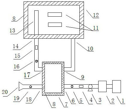
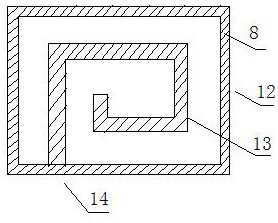
[0015] Such as figure 1 with figure 2 As shown, an air disinfection device includes a mask 1, a negative pressure chamber 2 installed behind the mask 1, and a fan 3 installed behind the negative pressure chamber 2 to form an air inlet section. The air after entering the air enters the air inlet of the plate heat exchanger 6 behind the fan 3, flows through the inner passage of the plate heat exchanger 7 to the air outlet of the plate heat exchanger 9, and absorbs heat in the plate heat exchanger 7 at the same time. The air is preheated and heated, and the virus is initially heated, dried, and dehydrated. The preheated air enters the thermostat 12 through the inlet 10 of the thermostat, exchanges heat with the surrounding objects in the thermostat 12, and is heated by the electric heating module 11 inside the thermostat. After the air is heated to the set temperature, it flows into the thermostat Copper gas pipe 13 in 12, after virus particle touches copper gas pipe 13 tube w...

Embodiment 2

[0017] Such as figure 1 As shown, the fan 3 inhales air from the mask 1 to the negative pressure chamber 2, and the negative pressure chamber 2 is a closed space of a circle, a square or other shapes. The negative pressure ensures that the air pressure in the negative pressure chamber 2 is lower than that of the mask 1. When the air pressure in the mask 1 rises, the negative pressure chamber 2 first absorbs the gas in the mask 1 to ensure that the gas does not leak out.

Embodiment 3

[0019] Such as figure 1 As shown, the flow meter-4 and the temperature sensor-5 are installed between the air outlet of the fan 3 and the air inlet-6 of the plate heat exchanger, and are used to detect the air flow and temperature of the air inlet-6 of the plate heat exchanger, and the flow rate Meter 2 15 and temperature sensor 2 16 are installed between the air outlet 14 of the thermostat and the inlet 17 of the plate heat exchanger to detect the air flow and temperature of the inlet 17 of the plate heat exchanger, and the temperature sensor 3 19 It is installed between the air outlet 18 and the air outlet 20 of the plate heat exchanger, and is used to detect the outlet air temperature.


PUM


Abstract

The invention discloses air disinfection equipment. A mask and a negative pressure chamber are arranged in front of a fan, a plate heat exchanger is arranged behind the fan, a thermostat is arranged behind the plate heat exchanger, and air discharged from the thermostat is sent to an air outlet through the plate heat exchanger. According to the air sterilization equipment, a high-temperature virus treatment technology is adopted, viruses are subjected to high-temperature drying and dehydration at a higher temperature and by prolonging the high-temperature time, then virus particles touch the high-temperature copper air pipe with excellent heat-conducting property for sufficient heat exchange, and then the viruses are rapidly cooled and dehydrated to inactivate the viruses, so that the purpose of killing the viruses is achieved.

Description

technical field [0001] The invention relates to the field of air purification, in particular to an air treatment device capable of killing viruses. Background technique [0002] Existing air disinfection equipment adopts technologies such as ultraviolet rays, ozone, plasma, and chemical methods. There are still limitations in the adaptability of various technologies in practical applications. Ultraviolet rays and ozone cannot be used in places where there are people. It is still difficult. These technologies are not perfect in dealing with low-density, high-flow gas disinfection such as air, and the speed is too slow to be miniaturized and made into portable or other wider applications. The existing equipment does not have a cavity to deal with the sharp change of the airflow, and it is easy for the virus to leak out in a non-fully enclosed environment. For example, in the field of patient exhaust treatment, the rapid airflow and suddenly increased airflow caused by coughin...

Claims


Application Information

Patent Timeline
IPC IPC(8): A61L9/16
CPCA61L9/16
Inventor 黄汉斌廖翊君
Owner 廖翊君
Why Eureka
Try Eureka