Fluid motion device for accelerating and energy-saving

A fluid and fluid layer technology, applied in transportation and packaging, hydrodynamic characteristics/hydrostatic characteristics, affecting the air flow flowing through the surface of the aircraft, etc., to achieve the effect of saving energy and simplifying the structure of the car

Inactive Publication Date: 2008-06-11
朱晓义
View PDF0 Cites 31 Cited by
  • Summary
  • Abstract
  • Description
  • Claims
  • Application Information

AI Technical Summary

Problems solved by technology

[0004] In order to overcome the above four kinds of resistance, the fluid wall is positive pressure, the fluid hole is side pressure, and t...

Method used


Image

  • Fluid motion device for accelerating and energy-saving
  • Fluid motion device for accelerating and energy-saving
  • Fluid motion device for accelerating and energy-saving

Examples


Embodiment Construction

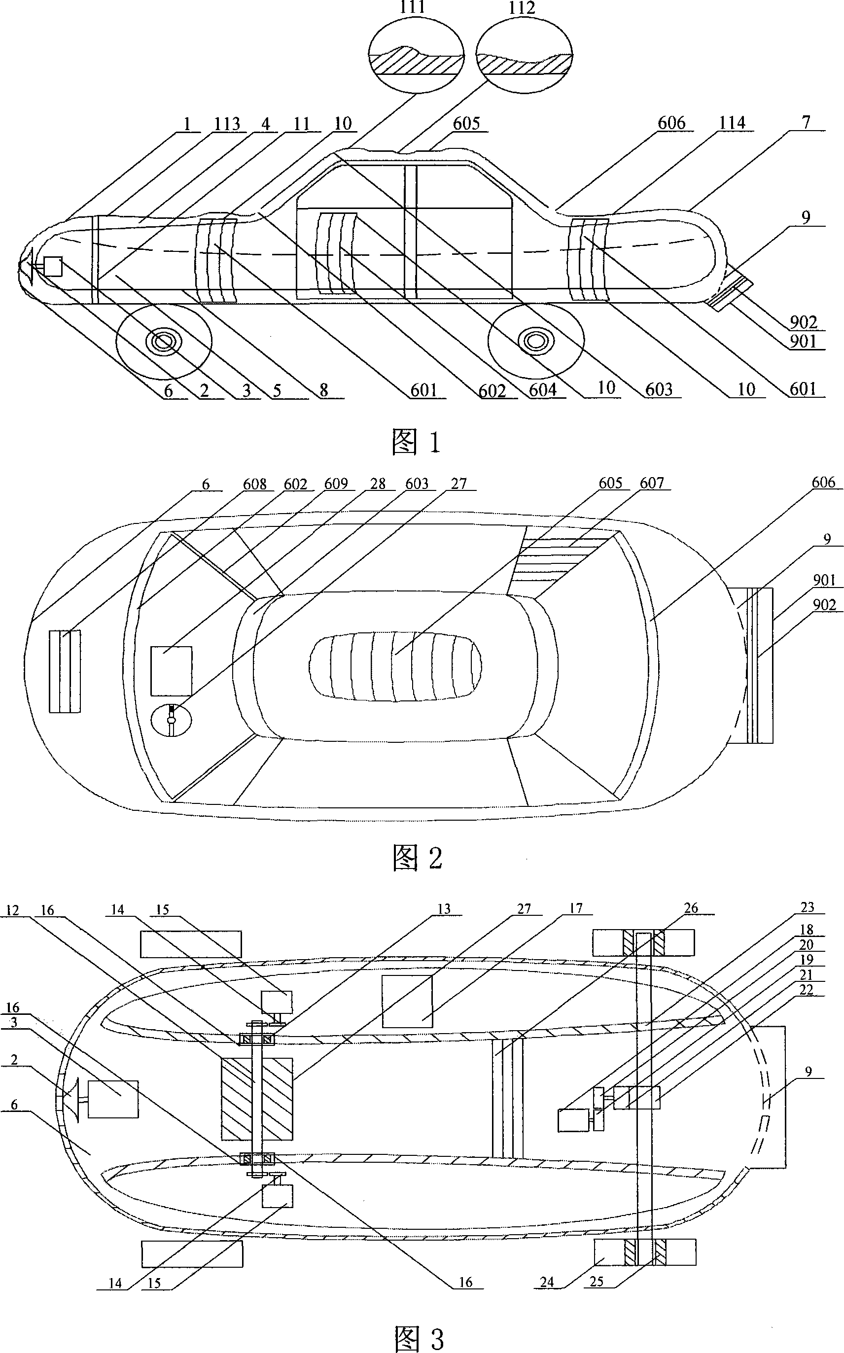
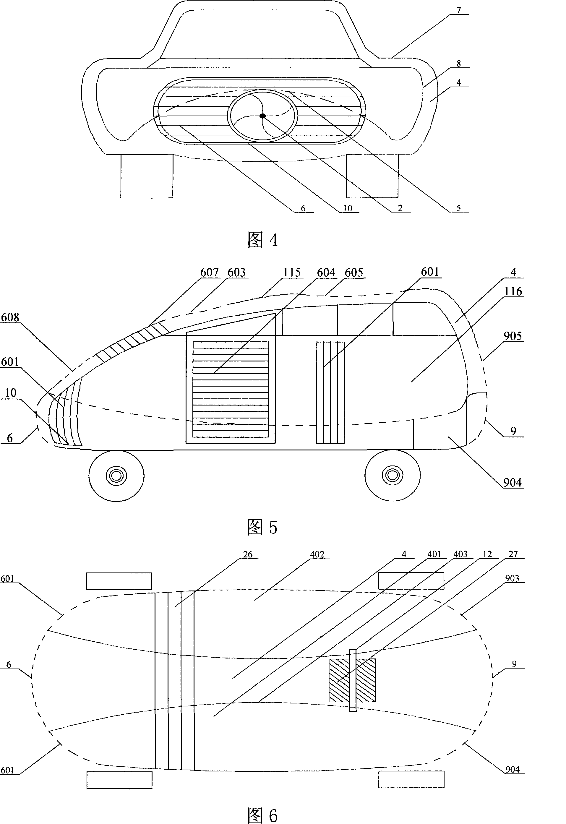
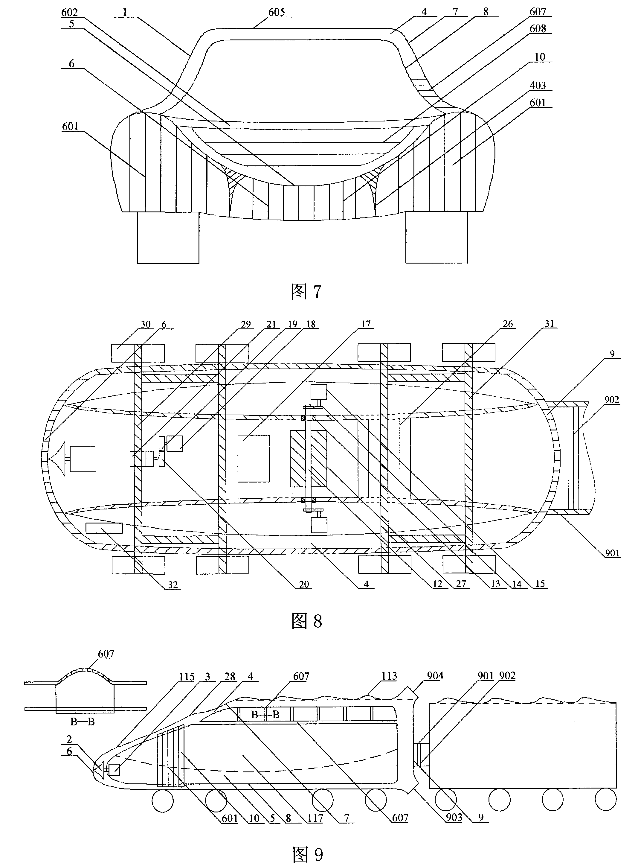
[0036] As shown in Figure 1-4: the outer shell 7 of the moving body 1 has an inner shell 8, and there is a fluid layer 4 between the inner shell 8 and the outer shell 7, and the inner shell 8 and the outer shell 7 are separated into fluid layers with a certain distance 4. Open a large hole at the front end of the shell 7 to connect the inlet 6 with the fluid layer 4 and the concave hole 5 in the fluid layer 4, open the outlet 9 at the rear end of the shell, and let the fluid introduced by the inlet 6 pass through the fluid layer 4 After passing through smoothly without hindrance, it is discharged from the exhaust port 901 of the outlet 9.

[0037] There is a flying saucer-shaped rotating head 2 in the middle of the inlet 6 for forming the fluid wall with the greatest resistance. There are four concave triangle lines on the contact surface between the rotating head and the fluid, which is convenient to cut the air flow. The rotating head 2 is driven by the motor 3 to rotate at a...


PUM

PropertyMeasurementUnit
Angleaaaaaaaaaa

Abstract

Provided is an accelerating and energy-saving moving device, a certain distance and a fluid layer are positioned between an outer case and an inner case of the device, the fluid layer is fore-and-aft communicated with a leading-in port arranged at the front end and a leading-out port mounted at the rear end, at least one leading-in port and one balance port which are arranged on the surrounding case body of the outer case are communicated with the fluid layer, the leading-in port, the balance port and the leading-in port which is arranged at the front end receive forward fluid, and the forward fluid is discharged from the leading-out port which is disposed at the middle portion or rear end of the device after passing through the fluid layer. An impeller and a generator are driven by the fluid layer to replenish energy source for fuel power and to drive a motor, a speed reducer, a differential mechanism and two half-spindles via a control panel, and the moving device is further driven to move. The invention further discloses energy-saving devices which employ the method, such as cars, trains, ships, submarines, airplanes, missiles, rockets and the like, the invention is in particular applicable to cars and trains. The resistance of a moving body in moving can be greatly reduced with the employment of the invention, and the energy consumption is greatly lowered, thereby the moving body can be accelerated extremely rapidly.

Description

Technical field: [0001] The invention relates to a moving energy-saving device, in particular to an energy-saving device moving at high speed in a fluid, which is applicable to devices and methods for trains, automobiles, ships, submarines, airplanes, rockets, missiles and the like moving in the fluid. Background technique: [0002] All moving bodies (such as automobiles, trains, rockets, missiles, ships, submarines, etc.) moving quickly in fluids need to consume a lot of energy to overcome resistance. Due to the rapid movement of the moving body in the fluid, it needs to consume a lot of energy to break away from the thick fluid wall (such as air and water) in front of the process. The energy forms a fluid hole in an instant, and the fluid hole is produced and disappeared in an instant as the moving device travels. However, the fluid hole tightly wraps the casing of the sports equipment, which brings great resistance. The moving body needs to spend the main energy to break...

Claims


Application Information

Patent Timeline
IPC IPC(8): B60L8/00B62D35/00B63B1/32B63H5/14B64C23/00
CPCY02T70/12Y02T10/7083Y02T30/32Y02T10/7072Y02T10/82Y02T10/88Y02T70/10
Inventor 朱晓义
Owner 朱晓义
Why Eureka
Try Eureka