Supporting jig

A fixture and support structure technology, applied in the field of machinery, can solve problems such as large deviations in multiple measurement results, incomplete test results, and incomplete measurement results, so as to ensure operation stability and accuracy, avoid repeated clamping, Effect of suppressing internal stress

Active Publication Date: 2021-12-21
湖南凌翔磁浮科技有限责任公司
View PDF6 Cites 0 Cited by
  • Summary
  • Abstract
  • Description
  • Claims
  • Application Information

AI Technical Summary

Problems solved by technology

In view of this situation, due to the complex internal force of mechanical parts, it is usually achieved by independent testing during the test process, which leads to incomplete test results
In addition, the existing independent test method not only makes the measurement results incomplete for irregular structural parts, but also often has the problem of large deviations in multiple measurement results due to different clamping methods

Method used


Image

  • Supporting jig
  • Supporting jig
  • Supporting jig

Examples


Embodiment Construction

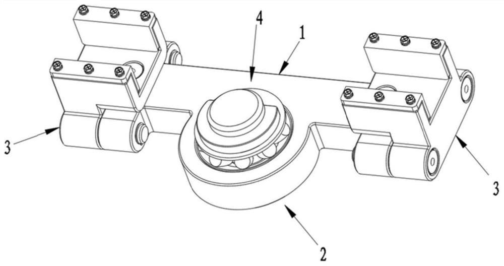
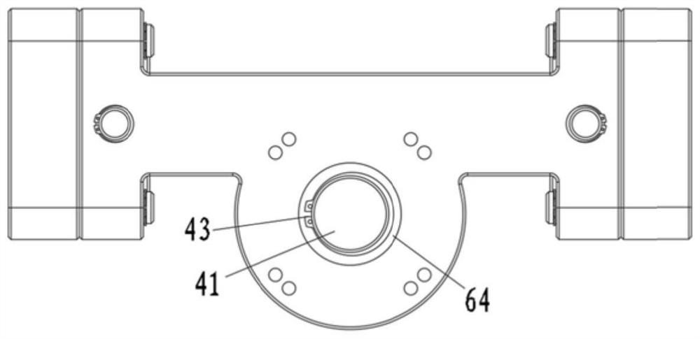
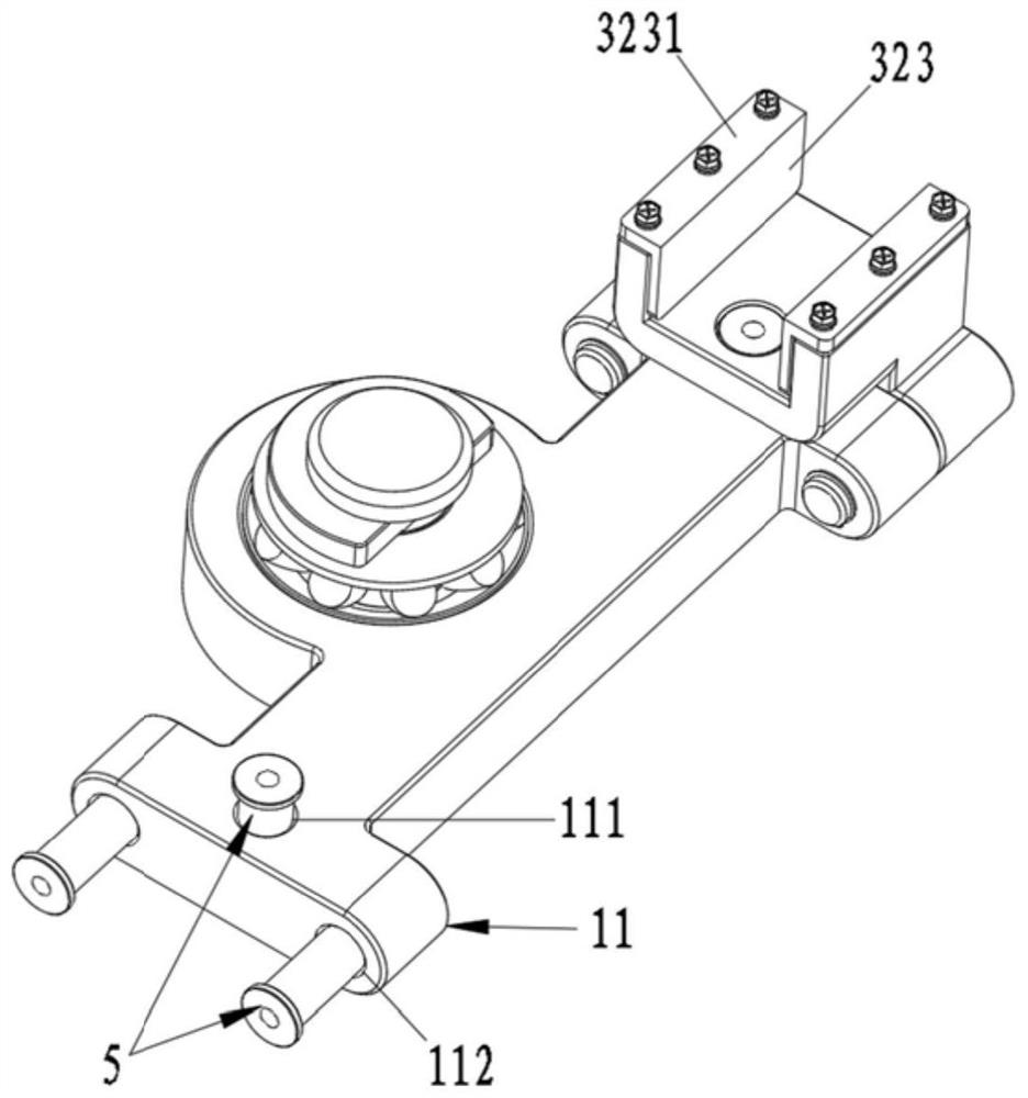
[0055] In order to more clearly describe the embodiments of the present invention or the technical solutions in the prior art, the following will briefly introduce the drawings that are used in the embodiments. Apparently, the drawings in the following description are only some embodiments of the present invention, and those skilled in the art can also obtain other drawings according to these drawings without creative efforts.

[0056] When describing the embodiments of the present invention, the terms "vertical", "transverse", "upper", "lower", "front", "rear", "left", "right", "vertical", " The orientation or positional relationship expressed by "horizontal", "top", "bottom", "inner", and "outer" is based on the orientation or positional relationship shown in the relevant drawings, which are only for the convenience of describing the present invention and simplifying the description, It is not intended to indicate or imply that the device or element referred to must have a p...


PUM


Abstract

The invention relates to a supporting jig. The supporting jig comprises a supporting main body (1), a mounting connecting part (2) connected with the supporting main body (1), positioning connecting parts (3) detachably mounted on the supporting main body (1), and a rotating support (4); the supporting main body (1) is of a long-strip-shaped structure, the mounting connecting part (2) is arranged at one side of the supporting main body (1) in the width direction in an offset mode, and the positioning connecting parts (3) are arranged at the two ends of the supporting main body (1) in the length direction respectively; and the rotating support (4) is arranged in the width direction of the supporting main body (1) in an offset mode, the rotating support (4) is connected with the mounting connecting part (2), or the rotating support (4) is connected with the mounting connecting part (2) and the supporting main body (1).

Description

technical field [0001] The invention relates to the mechanical field, in particular to a supporting jig. Background technique [0002] In the field of mechanical manufacturing, the workpieces produced usually need to be effectively tested for the working load of the workpiece before they are put into production. Only when the obtained test results meet the relevant requirements can they be used in large-scale production. The test items for different mechanical components are also different, and for most mechanical components, it is more common to be subjected to working loads in multiple directions at the same time during the working process. In view of this situation, due to the complex internal force of the mechanical parts, it is usually achieved by independent testing during the testing process, which leads to incomplete test results. In addition, the existing independent test method not only makes the measurement results incomplete for irregular structural parts, but a...

Claims


Application Information

Patent Timeline
Patent Type & Authority Applications(China)
IPC IPC(8): B25B11/00G01M13/00
CPCB25B11/00G01M13/00
Inventor 周文武涂俊袁伟张兴华黄梦凡
Owner 湖南凌翔磁浮科技有限责任公司
Why Eureka
Try Eureka