Comprehensive temperature-control electromagnetic clutch

An electromagnetic clutch, electromagnet technology, applied in the direction of magnetic drive clutch, clutch, non-mechanical drive clutch, etc., can solve the problem of limited cooling range, temperature rise, affecting the stability and service life of electromagnetic clutch, to ensure the work. Stability and longevity, the effect of efficient heat absorption

Active Publication Date: 2017-06-20
GUANGDE COUNTY HUIDA ELECTRICAL APPLIANCES
View PDF14 Cites 0 Cited by
  • Summary
  • Abstract
  • Description
  • Claims
  • Application Information

AI Technical Summary

Problems solved by technology

Solid, this kind of cooling device has the problem of energy waste, in order to solve this problem, some existing cooling devices use electromagnetic clutches and temperature control switches to control the cooling time, such as the Chinese patent No. ZL201420021271.0 discloses a The electromagnetic clutch fan cooling device for engineering machinery engines, which is connected to the inner and outer coils of the electromagnet through two temperature control switches to achieve timely cooling and cooling intensity
However, this device only achieves cooling by changing the rotating speed of the fan, and its cooling range is limited, which cannot meet the cooling needs of working for a long time in a hot climate
[0003] In addition, while this type of electromagnetic clutch cools down other equipment, it will increase the temperature of the entire electromagnetic clutch and the temperature of its working environment due to frictional heat generated during frequent clutching and long-term rotation, thereby Affects the stability and service life of the electromagnetic clutch, so a device that can avoid the overheating of the electromagnetic clutch is needed

Method used


Image

  • Comprehensive temperature-control electromagnetic clutch
  • Comprehensive temperature-control electromagnetic clutch
  • Comprehensive temperature-control electromagnetic clutch

Examples


Embodiment 1

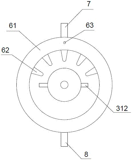
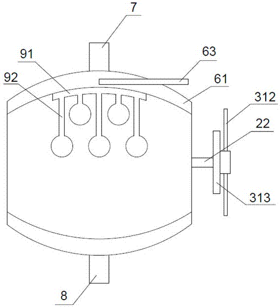
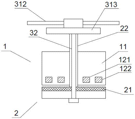
[0032] Example 1, such as Figure 1-5 As shown, the present invention includes a cooling assembly and a self-radiating assembly arranged outside the cooling assembly. The cooling assembly includes an active part 1, a driven part 2, a temperature control mechanism connected to the active part 1, and the The cooling mechanism connected to the driven part 2, the active part 1 includes a pulley 11, an electromagnet arranged in the pulley 11, the driven part 2 includes an armature 21, and a driving mechanism arranged in the middle of the armature 21. Shaft 22, the electromagnet includes an inner coil 121 and an outer coil 122; the temperature control mechanism includes a first temperature control switch connected to the outer coil 122 and a second temperature control switch connected to the inner coil 121; The cooling mechanism includes an air-cooling device connected to the drive shaft 22, a cooling pipe 32 arranged in the drive shaft 22 and connected to the air-cooling device; th...


PUM


Abstract

The invention provides a comprehensive temperature-control electromagnetic clutch and belongs to the technical field of electromagnetic clutches. The comprehensive temperature-control electromagnetic clutch comprises a cooling assembly and an automatic heat dissipating assembly, wherein the cooling assembly comprises a driving part, a driven part, a temperature-control mechanism and a cooling mechanism; the driving part comprises a belt pulley and an electromagnet; the driven part comprises an armature and a driving shaft; the electromagnet comprises an inner coil and an outer coil; the temperature-control mechanism comprises a first temperature-control switch and a second temperature-control switch; the first temperature-control switch is connected with the outer coil; the second temperature-control switch is connected with the inner coil; the cooling mechanism comprises an air cooling device and a cooling pipe; the air cooling device is connected with the driving shaft; the cooling pipe is arranged in the driving shaft and communicates with the air cooling device; the automatic heat dissipating assembly comprises a heat absorbing device, a heat exhaust pipe arranged above the heat absorbing device, and an air inlet pipe arranged below the heat absorbing device; the heat absorbing device comprises a ring cavity, a plurality of heat absorbing parts arranged on the inner side wall of the ring cavity, and a liquid inlet pipe arranged on one side of the upper part of the ring cavity; and the liquid inlet pipe is equipped with a temperature-control switch. By adoption of the comprehensive temperature-control electromagnetic clutch provided by the invention, other devices can be effectively cooled within a wide range; and meanwhile, the working temperature of the comprehensive temperature-control electromagnetic clutch can be controlled.

Description

technical field [0001] The invention relates to the technical field of electromagnetic clutches, in particular to a fully temperature-controlled electromagnetic clutch. Background technique [0002] Because some existing equipment will generate heat during work, a cooling device is often provided to control the temperature, so as to ensure the normal operation and service life of the equipment. However, many existing cooling devices are generally started and shut down at the same time as the equipment they serve, and this type of equipment does not need to be in a cooling state all the time, it only needs to avoid its temperature being too high. Solid, this kind of cooling device has the problem of energy waste, in order to solve this problem, some existing cooling devices use electromagnetic clutches and temperature control switches to control the cooling time, such as the Chinese patent No. ZL201420021271.0 discloses a The electromagnetic clutch fan cooling device for eng...

Claims


Application Information

Patent Timeline
Patent Type & Authority Applications(China)
IPC IPC(8): F16D27/14F16D27/00
CPCF16D27/00F16D27/14
Inventor 杜辉
Owner GUANGDE COUNTY HUIDA ELECTRICAL APPLIANCES
Why Eureka
Try Eureka