Eureka AIR delivers breakthrough ideas for toughest innovation challenges, trusted by R&D personnel around the world.

Oil gun integrating vehicle-mounted oil gas recovery system and gas station secondary oil gas recovery system and oiling machine

A technology of oil gas recovery system and refueling gun, which is applied in the field of refueling guns, and can solve problems such as incompatibility, fugitive discharge of PV valves, high pressure, etc.

Pending Publication Date: 2021-12-21
CHINA PETROLEUM & CHEM CORP +1
View PDF0 Cites 0 Cited by
  • Summary
  • Abstract
  • Description
  • Claims
  • Application Information

AI Technical Summary

Problems solved by technology

However, there are certain differences between the vehicle-mounted oil vapor recovery system and the secondary oil vapor recovery system due to the design and operating parameters. There will be some incompatibility when refueling vehicles in the system. The problems include that the oil vapor recovery vacuum pump cannot extract oil vapor during the refueling process, causing the shutdown due to excessive pressure, or excess air being pumped back to the underground oil storage tank, resulting in fugitive emissions from the PV valve.

Method used


Image

  • Oil gun integrating vehicle-mounted oil gas recovery system and gas station secondary oil gas recovery system and oiling machine
  • Oil gun integrating vehicle-mounted oil gas recovery system and gas station secondary oil gas recovery system and oiling machine
  • Oil gun integrating vehicle-mounted oil gas recovery system and gas station secondary oil gas recovery system and oiling machine

Examples


Embodiment Construction

[0029] It should be noted that, in the case of no conflict, the embodiments and features in the embodiments of the present invention can be combined with each other.

[0030] In the present invention, it should be understood that the orientations or positional relationships indicated by the terms "deviating from", "facing", "circumferential", "axial" and the like are based on the orientations or positional relationships shown in the drawings, and are also different from the actual The used orientation or positional relationship corresponds to each other; "front and rear" refer to the front and rear directions of the fuel gun, and the specific nozzle head of the fuel gun refers to the front, and the gun body is the rear; "inner and outer" refers to Inner and outer relative to the contours of the parts themselves are not intended to indicate that a referenced device or element must have a particular orientation, be constructed and operate in a particular orientation and therefore...


PUM


Abstract

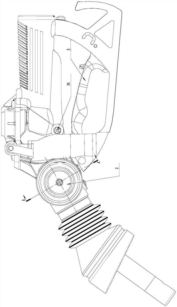
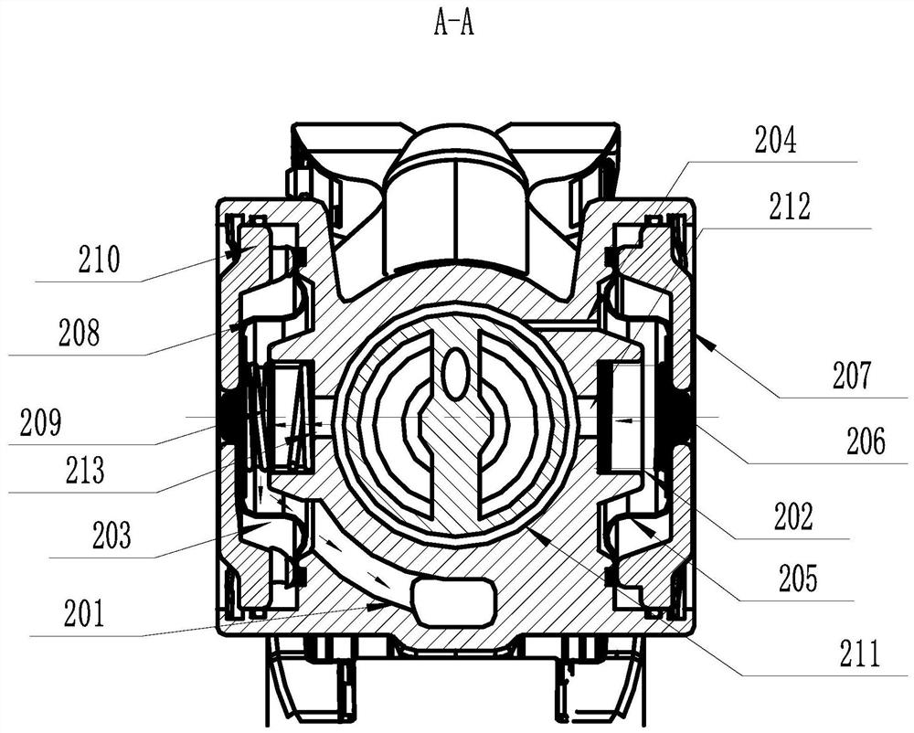
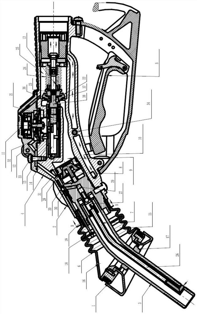
The invention relates to the technical field of oil guns, and discloses an oil gun integrating a vehicle-mounted oil gas recovery system and a gas station secondary oil gas recovery system and an oiling machine. The oil gun comprises a vehicle-mounted oil gas recovery sensing valve, and a first valve part and a second valve part are located on the two radial opposite sides of a valve seat. A first valve cavity is defined by the first valve part, and the first valve part comprises a first diaphragm and a first valve part spring connected to the first diaphragm and the valve seat. A second valve cavity, a second diaphragm and a second valve part spring connected to the second diaphragm and the valve seat are defined by the second valve part. The valve seat is provided with a first valve seat through hole, a throttling through hole and a second valve seat through hole, a valve seat gas circuit is arranged in the valve seat, the first valve seat through hole and the throttling through hole communicated with the valve seat gas circuit and the first valve cavity correspondingly, the second valve seat through hole communicates with the valve seat gas circuit and the second valve cavity, and the first valve seat through hole and the second valve seat through hole are plugged by the first diaphragm and the second diaphragm correspondingly. A front gas path and a rear gas path are formed in the oil gun, the front end of the first valve cavity communicates with the front gas path, and the rear end of the second valve cavity communicates with the rear gas path.

Description

technical field [0001] The invention relates to the technical field of refueling guns, in particular to a refueling gun and a refueling machine that take into account both a vehicle-mounted oil and gas recovery system and a secondary oil and gas recovery system at a gas station. Background technique [0002] In December 2016, GB18352.6-2016 "Limits and Measurement Methods of Pollutant Emissions from Light-duty Vehicles", namely the National Sixth Standard, was released. In order to meet the requirements of the standard, domestic sales vehicles need to upgrade the on-board oil vapor recovery (ORVR) system from 2020. The oil and gas recovery efficiency of the vehicle-mounted oil and gas recovery system is as high as 98%. Once it is widely promoted, it will replace the secondary oil and gas recovery equipment. [0003] However, at present, most of the domestic gas stations are installed with the secondary oil and gas recovery system previously installed. The secondary oil and g...

Claims


Application Information

Patent Timeline
Patent Type & Authority Applications(China)
IPC IPC(8): B67D7/54
CPCB67D7/54
Inventor 修德欣王振中赵雯晴丁莉丽贾光
Owner CHINA PETROLEUM & CHEM CORP
Why Eureka
Eureka Blog
Learn More