Pipeline system for rainwater source emission reduction and laying method

A technology of pipeline system and source, applied in the direction of sewer pipeline system, waterway system, water supply device, etc.

Pending Publication Date: 2021-12-21
民航机场规划设计研究总院有限公司
View PDF0 Cites 0 Cited by
  • Summary
  • Abstract
  • Description
  • Claims
  • Application Information

AI Technical Summary

Problems solved by technology

[0006] The purpose of the present invention is to provide a pipeline system and layout method for reducing discharge from the source of rainwater, so as to reduce the technical problem of the load borne by the drainage and risk relief equipment and facilities in the airport flight area when the rain peak arrives

Method used


Image

  • Pipeline system for rainwater source emission reduction and laying method
  • Pipeline system for rainwater source emission reduction and laying method
  • Pipeline system for rainwater source emission reduction and laying method

Examples


Embodiment Construction

[0032] In order for those skilled in the art to better understand the technical solutions provided by the present invention, the technical solutions in the embodiments of the present application will be clearly and completely described below in conjunction with the drawings in the embodiments of the present application. Obviously, the described The embodiments are only some of the embodiments of the present application, but not all of them. Based on the embodiments in this application, all other embodiments obtained by persons of ordinary skill in the art without making creative efforts belong to the scope of protection of this application.

[0033] If the scattered soil area in the flight area can be effectively used to realize artificially controllable dispersed stagnation, the peak runoff will be dispersed to a certain extent, the peak runoff will be lowered, and the peak runoff will be staggered, thereby greatly sharing the load of terminal facilities and reducing the airpo...


PUM


Abstract

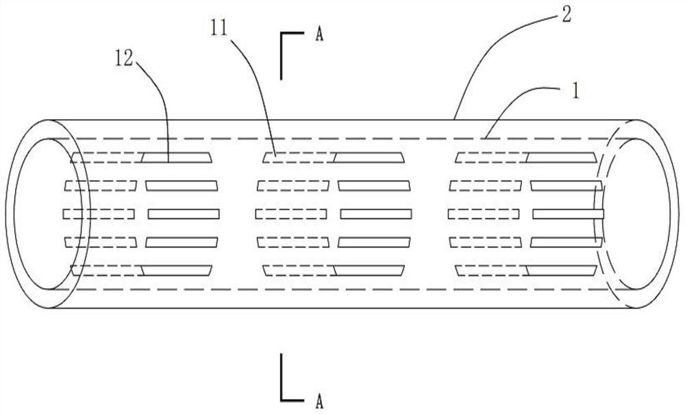
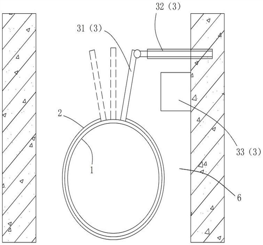
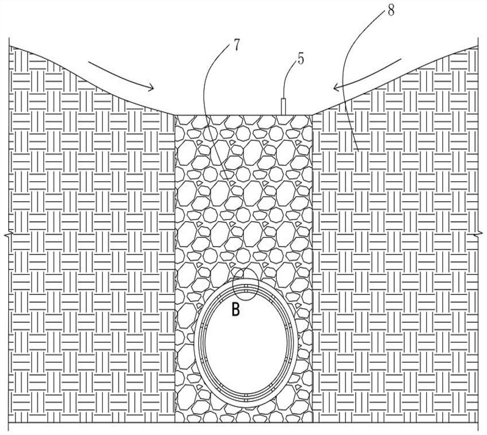
The invention provides a pipeline system for rainwater source emission reduction and a laying method, and relates to the field of airport engineering. The pipeline system comprises a first pipe body, a second pipe body and a driving structure, wherein a first water collecting hole is formed in the first pipe body; the second pipe body is arranged outside the first pipe body in a sleeving manner; the second pipe body is movably connected with the first pipe body; a second water collecting hole is formed in the second pipe body; and the driving structure is used for regulating and controlling the position of the first water collecting hole relative to the second water collecting hole. Compared with the prior art, the pipeline system for rainwater source emission reduction has the advantages that the driving structure is used for regulating and controlling the operation states of the first pipe body and the second pipe body, so that the first water collecting hole and the second water collecting hole are respectively in a staggered or communicated operation state. Therefore, autonomous control on a downward seepage or non-seepage mode is realized. The dispersion or retention of rainwater can be realized by utilizing a soil surface area in a flight area, so that the purposes of peak regulation and peak staggering are achieved.

Description

technical field [0001] The patent of the present invention relates to the field of airport engineering, in particular to a pipeline system and layout method for reducing discharge of rainwater at the source. Background technique [0002] With the in-depth implementation of the national "sponge city" concept in the construction and municipal industries, its core six-character policy of "seepage, stagnation, storage, purification, use, and drainage" has been proven to be effective in alleviating urban waterlogging and protecting people. Engineering measures for the safety of life and property. Similarly, how to comprehensively and effectively build a safe and green sponge airport has become a new hot spot under the strong impetus of the "four-type airport" construction concept of the Civil Aviation Administration of China. [0003] In a safe airport, waterlogging safety is a core requirement; this raises questions about how to use storage pools in the airport to achieve peak ...

Claims


Application Information

Patent Timeline
Patent Type & Authority Applications(China)
IPC IPC(8): E03F3/02E03F3/04E03F3/06
CPCE03F3/02E03F3/04E03F3/06E03F2201/20
Inventor 李琛
Owner 民航机场规划设计研究总院有限公司
Why Eureka
Try Eureka