Check patentability & draft patents in minutes with Patsnap Eureka AI!

Semi-automatic chip testing machine and working method

A chip testing, semi-automatic technology, applied in the direction of electronic circuit testing, measuring electricity, measuring devices, etc., can solve the problems of high labor cost, low efficiency, affecting testing efficiency, etc., and achieve the effect of cost saving

Pending Publication Date: 2021-12-21
深圳市宏旺微电子有限公司
View PDF0 Cites 0 Cited by
  • Summary
  • Abstract
  • Description
  • Claims
  • Application Information

AI Technical Summary

Problems solved by technology

This manual operation method is very inefficient and requires a lot of labor costs, and it is prone to errors in any link in the test process, which affects the test efficiency.

Method used


Image

  • Semi-automatic chip testing machine and working method
  • Semi-automatic chip testing machine and working method
  • Semi-automatic chip testing machine and working method

Examples


Embodiment 1

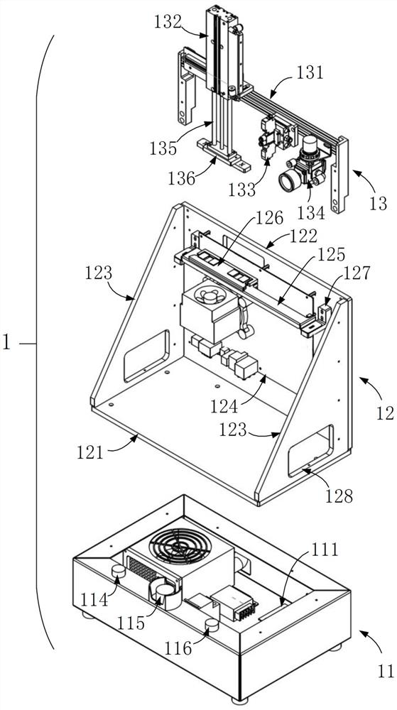
[0049] This example figure 1 As shown, it is a semi-automatic chip testing machine 1 , which includes a testing base 11 , a testing platform 12 and an action mechanism 13 .

[0050] In this embodiment, the test machine base 12 is a rectangular parallelepiped, and a control board 111 is installed inside the test machine base 12. The control board 111 is used to control the test platform 12 to perform a test action and to control the action mechanism 13 to perform a pressing action.

[0051]It should be noted that the test base 12 is preferably in the shape of a cuboid, and may also be in the shape of a cube, or a polygonal shape that can satisfy the technical solution, which is not limited in this embodiment.

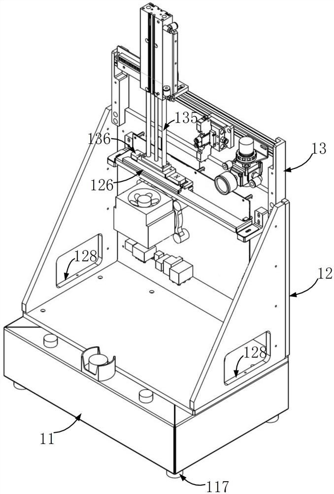
[0052] In this embodiment, the four corners at the bottom of the test stand 11 can also be provided with a leg 117 (such as figure 2 As shown), the height of the feet 117 can be adjusted, so the semi-automatic chip testing machine 1 recorded in this technical solution ...

Embodiment 2

[0088] The difference between this embodiment and embodiment 1 is that this embodiment is a working method applied to embodiment 1, and its specific working method is as follows (the work flow chart is as follows Figure 5 shown):

[0089] S101. Power on the test machine (or semi-automatic chip test machine):

[0090] In this embodiment, the step S101 is specifically: the external power supply is connected to the power interface 112 of the test machine, and then the power switch button 113 is turned on, so that the semi-automatic chip test machine 1 is powered on It should be pointed out that the external power supply in this embodiment is common commercial power, and the commercial power needs to be transformed and rectified before it can be used by the test machine after it is connected to the test machine.

[0091] S102. Loading the chip to be tested:

[0092] In this embodiment, the step S102 is specifically: the operator manually loads the chip to be tested (in this emb...


PUM


Abstract

The invention discloses a semi-automatic chip testing machine table and a working method. The semi-automatic chip testing machine table comprises a testing machine base, a testing table and an action mechanism, wherein the testing table is arranged on the testing machine base and is an open box body composed of a bottom plate, a back plate, a left supporting plate and a right supporting plate, and the testing table is used for placing a testing chip and executing a testing action; the action mechanism comprises an air cylinder, is arranged at a top end of the testing table and is used for automatically pressing the testing chip. The working method comprises the following steps of S101, electrifying the testing table; S102, loading a chip to be tested; S103, starting a chip test; S104, ending the chip test; and S105, outputting the chip test result. According to the method, the whole testing process is controlled by a program, human participation is reduced, testing efficiency of a memory chip is greatly improved, the error rate of pure manual testing is reduced, semi-automatic testing of the memory chip can be achieved, and a purpose of saving cost for enterprises can be achieved.

Description

technical field [0001] The invention relates to the technical field of chip testing, in particular to a semi-automatic chip testing machine and a working method. Background technique [0002] Memory chips are often called "memory particles". Memory chips are the core components of storage devices. The quality of memory chips can directly affect the performance of storage devices. Because the chip has a certain defect rate, the memory chip must be strictly tested before its application. [0003] In the prior art, the memory chip is often tested manually, such as loading the memory chip into a specific jig, and then the worker inserts the jig with the memory chip into the test equipment, and then performs the test. After the test, the worker Pull the clamp off manually. This manual operation method is very inefficient, requires a lot of labor costs, and is prone to errors in any link in the testing process, thereby affecting the testing efficiency. [0004] In view of this,...

Claims


Application Information

Patent Timeline
IPC IPC(8): G01R31/28G01R1/04
CPCG01R31/2851G01R31/2863G01R1/0408
Inventor 杨密凯杨松坤李斌
Owner 深圳市宏旺微电子有限公司
Features
  • R&D
  • Intellectual Property
  • Life Sciences
  • Materials
  • Tech Scout
  • Unparalleled Data Quality
  • Higher Quality Content
  • 60% Fewer Hallucinations
Learn More