Laser cutting equipment convenient to clean

A laser cutting and equipment technology, applied in laser welding equipment, welding equipment, metal processing equipment, etc., can solve problems such as enterprise loss, laser head damage, and inconvenient cleaning.

Pending Publication Date: 2021-12-24
ZHEJIANG JINAOLAN MASCH TOOL CO LTD
View PDF0 Cites 6 Cited by
  • Summary
  • Abstract
  • Description
  • Claims
  • Application Information

AI Technical Summary

Problems solved by technology

[0002] Due to its high cutting efficiency, laser cutting equipment has become an indispensable equipment for enterprises. During the use of laser cutting equipment, since the plate is directly placed on the support plate of the laser cutting equipment, the laser cuts the plate while , the slag of the melted plate will stick to the support plate, which is very inconvenient to clean, and because the support plates of the cutting equipment currently used are generally spaced rack-shaped support plates, the gap between the two rack-shaped support plates The distance is a fixed value, and the rack-shaped support plate is fixed on the cutting equipment, so when the material to be cut is slightly larger than the interval distance, one end will be lifted, and the other end will touch the side of the rack-shaped support plate , do not fall into the collection bucket at the bottom, because one end is tilted, the laser head will touch the laser head when passing through this area, which will cause damage to the laser head or trigger an alarm, and the entire equipment will stop working, resulting in damage to the enterprise loss

Method used


Image

  • Laser cutting equipment convenient to clean
  • Laser cutting equipment convenient to clean
  • Laser cutting equipment convenient to clean

Examples


Embodiment 1

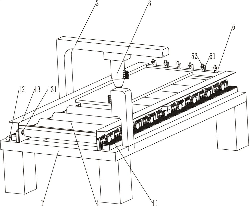
[0035] The present invention will be described in further detail below in conjunction with accompanying drawing and specific embodiment: see Figure 1-Figure 4 ,

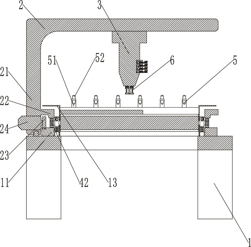
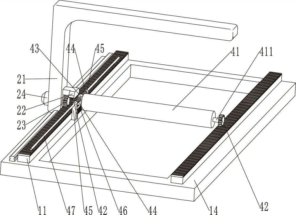
[0036] A laser cutting device that is easy to clean, including a base 1, a three-coordinate walking part 2, a laser head 3, a bearing part 4 and a pressing device 5, the laser head 3 is arranged on the three-coordinate walking part 2, and the three-coordinate walking part 2 is set On the base 1, it is used to drive the laser head 3 to move in the X-axis, Y-axis and Z-axis. The three-coordinate walking part 2 includes a walking frame 21, a moving rack 22, a traveling gear 23 and a driving motor 24. The moving rack 22 is arranged on the walking frame 21 , the driving motor 24 is arranged on the walking frame 21 , and the traveling gear 23 is arranged on the driving motor 24 .

[0037] The base 1 includes a fixed rack 11, a guide rail 12 and a frame 14. The fixed rack 11 is arranged on the left and right sides of the ...

Embodiment 2

[0053] The present invention will be described in further detail below in conjunction with accompanying drawing and specific embodiment: see Figure 1-Figure 14 ,

[0054] A laser cutting device that is easy to clean, including a base 1, a three-coordinate walking part 2, a laser head 3, a bearing part 4, a pressing device 5, an anti-light pollution device 6, a spraying device 7, a calibration reset device 8, and an outer cover frame 61 , the laser head 3 is set on the three-coordinate walking part 2, and the three-coordinate walking part 2 is set on the base 1, which is used to drive the laser head 3 to move on the X-axis, Y-axis and Z-axis, and the anti-light pollution device 6 is set on the laser head 3, used to block the strong light generated when the laser is working, the spraying device 7 is arranged on the laser head 3, and the correction and reset device 8 is arranged on the base 1, and the spraying device 7 and the correction and reset device 8 are arranged in cooper...


PUM


Abstract

The invention discloses a laser cutting equipment convenient to clean. The laser cutting equipment comprises a base, a three-coordinate walking part, a laser head and a bearing part, the laser head is arranged on the three-coordinate walking part, the three-coordinate walking part is arranged on the base and used for driving the laser head to move on the X axis, the Y axis and the Z axis, and the three-coordinate walking part comprises a walking frame and a moving rack. According to the laser cutting equipment with a rolling wheel replacing a plate supporting plate, when the laser head moves to the position below the rolling wheel, the rolling wheel can be automatically moved away, therefor, slag cannot be attached to the rolling wheel, cleaning of the rolling wheel is avoided, the cutting equipment is convenient to clean, meanwhile, the rolling wheel is automatically moved away, a cut plate can conveniently fall off, laser equipment failures caused by the fact that the plate do not fall off and is clamped on the supporting plate are avoided, the service life of laser cutting equipment is prolonged, the working efficiency of the equipment is improved, the maintenance cost is reduced, and the enterprise burden is relieved.

Description

technical field [0001] The invention relates to the technical field of laser cutting equipment, in particular to a laser cutting equipment that is easy to clean. Background technique [0002] Due to its high cutting efficiency, laser cutting equipment has become an indispensable equipment for enterprises. During the use of laser cutting equipment, since the plate is directly placed on the support plate of the laser cutting equipment, the laser cuts the plate while , the slag of the melted plate will stick to the support plate, which is very inconvenient to clean, and because the support plates of the cutting equipment currently used are generally spaced rack-shaped support plates, the gap between the two rack-shaped support plates The distance is a fixed value, and the rack-shaped support plate is fixed on the cutting equipment, so when the material to be cut is slightly larger than the interval distance, one end will be lifted, and the other end will touch the side of the r...

Claims


Application Information

Patent Timeline
Patent Type & Authority Applications(China)
IPC IPC(8): B23K26/38B23K26/70B23K26/142B23K26/16B05B13/02
CPCB23K26/38B23K26/702B23K26/16B23K26/142B05B13/0278
Inventor 吕时广陈勇良李立真王静王灵英叶建林张天伟郑群强
Owner ZHEJIANG JINAOLAN MASCH TOOL CO LTD
Why Eureka
Try Eureka