
Sinking construction device for cast-in-place underground building

A technology for underground buildings and construction devices, which is applied in the directions of buildings, hoisting devices, underwater structures, etc., can solve the problems of easy inclination deviation, easy breaking of chain knives, high power of driving devices, etc. The effect of control, chain tension is small, and it is not easy to break

Pending Publication Date: 2021-12-28
POWERCHINA HUADONG ENG COPORATION LTD +3
View PDF0 Cites 0 Cited by
  • Summary
  • Abstract
  • Description
  • Claims
  • Application Information

AI Technical Summary

Problems solved by technology

[0002] Existing large-scale underground buildings are usually constructed by the open-cut method. The open-cut method needs to excavate the foundation pit first for support, and then pour or assemble the underground building in the foundation pit. Temporary support and dewatering of the foundation pit are required. The construction period is long and the cost is high; At present, chain cutters are used to excavate the bottom rock and soil, and the technical scheme of overall sinking, and the sinking construction without hanging devices, because the load of the underground building itself is too heavy, has the following defects: it is easy to produce tilt and offset, and it needs to be added when sinking. Correction device, and once deviation occurs, it is difficult to achieve deviation correction; such a large load is pressed on the bottom chain knife, resulting in too much power of the drive device, and the chain knife is easy to break; the descending speed is difficult to control; the bottom chain knife The cutting amount is out of control, and the cutting tool is easily damaged; for this reason, we propose a sinking construction device for cast-in-place underground buildings to solve the above problems

Method used


Image

  • Sinking construction device for cast-in-place underground building
  • Sinking construction device for cast-in-place underground building
  • Sinking construction device for cast-in-place underground building

Examples


Embodiment Construction

[0028] The technical solutions in the embodiments of the present invention will be clearly and completely described below in conjunction with the accompanying drawings in the embodiments of the present invention. Obviously, the described embodiments are only some of the embodiments of the present invention, not all of them. Based on The embodiments of the present invention and all other embodiments obtained by persons of ordinary skill in the art without making creative efforts belong to the protection scope of the present invention.

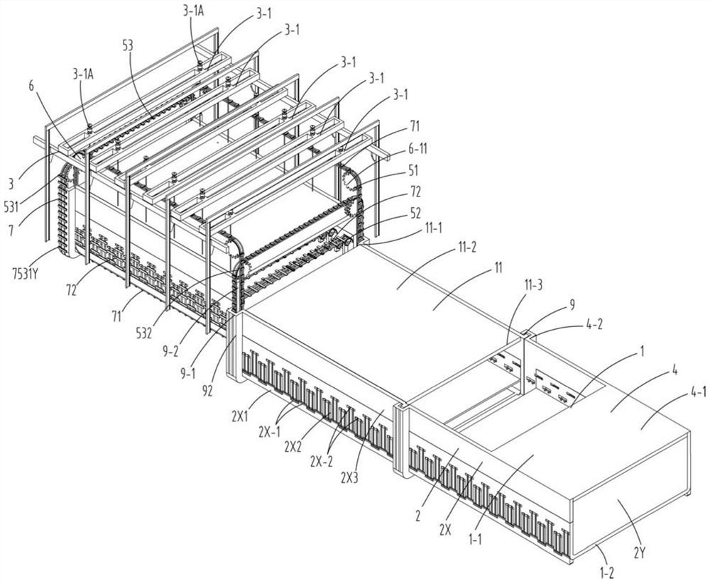
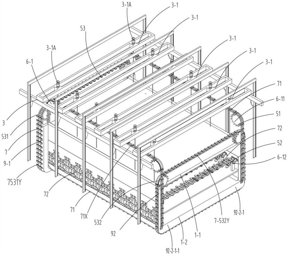
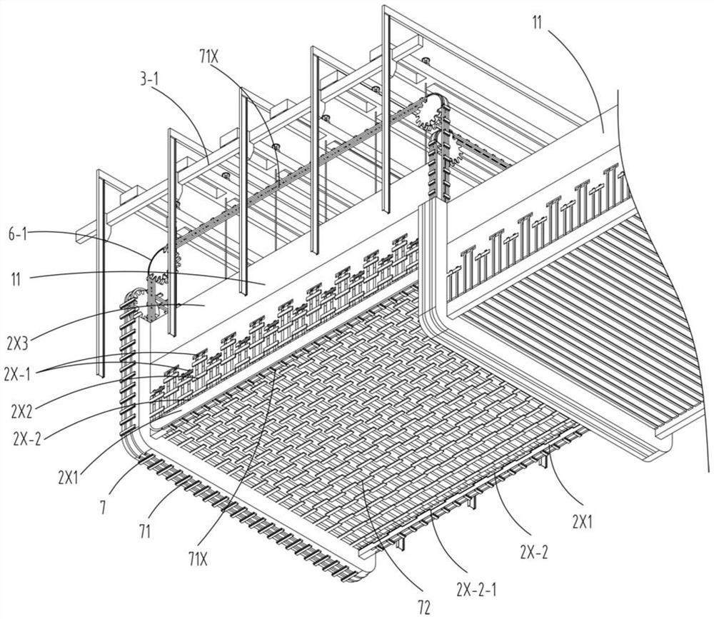
[0029] see Figure 1-11 , in the embodiment of the present invention, the building 1 located underground comprises an outer wall 2, a top plate 1-1, a bottom plate 1-2 and a construction device 3, and is composed of end sections 4 at both ends and an intermediate section 11 in the middle, and the outer wall 2 includes a longitudinal wall 2X and a transverse wall 2Y, the end section 4 includes a transverse wall 2Y at the end and two longitudinal ...


PUM


Abstract

The invention discloses a sinking construction device for a cast-in-place underground building, and relates to the technical field of underground building construction. The underground building comprises an outer wall, a top plate, a bottom plate and a construction device, and is composed of end sections located at the two ends and a middle section located in the middle, and the outer wall comprises a longitudinal wall and a transverse wall; the construction device comprises an excavating device, a hanging device located at the top of the building and a pouring device, the excavating device comprises an outer wall excavating device and a bottom plate excavating device, the outer wall excavating device excavates rock soil at the bottom of the outer wall, the bottom plate excavating device excavates rock soil at the bottom of the bottom plate, the outer wall excavating device and the bottom plate excavating device comprise chain cutter excavating devices, and each chain cutter excavating device comprises a chain cutter and a driving device; and a longitudinal wall comprises upper holes and lower holes, the upper holes are vertically staggered, the lower holes are vertically staggered, the upper holes are located above the bottom plate, the lower holes are next to the lower portion of the bottom plate, the bottom plate chain cutter envelops the bottom plate through the upper holes and the lower holes, and the longitudinal wall comprises a lower longitudinal wall located below the bottom plate, a middle longitudinal wall located between the upper holes and the lower holes and an upper longitudinal wall located above the upper holes.

Description

technical field [0001] The invention relates to the technical field of underground building construction, in particular to a sinking construction device for cast-in-place underground buildings. Background technique [0002] Existing large-scale underground buildings are usually constructed by the open-cut method. The open-cut method needs to excavate the foundation pit first for support, and then pour or assemble the underground building in the foundation pit. Temporary support and dewatering of the foundation pit are required. The construction period is long and the cost is high; At present, chain cutters are used to excavate the bottom rock and soil, and the technical scheme of overall sinking, and the sinking construction without hanging devices, because the load of the underground building itself is too heavy, has the following defects: it is easy to produce tilt and offset, and it needs to be added when sinking. Correction device, and once deviation occurs, it is diffic...

Claims


Application Information

Patent Timeline
Patent Type & Authority Applications(China)
IPC IPC(8): E02D29/045E02D15/02E02D15/08E02F5/06E02F5/14B66C13/08B66F3/24B66F7/04B66F7/28
CPCE02D29/045E02D15/02E02D15/08E02F5/06E02F5/14B66C13/08B66F3/24B66F7/04B66F7/28
Inventor 徐杭杰陈金苗王志虹臧延伟王燏斌王树生邬紫珊
Owner POWERCHINA HUADONG ENG COPORATION LTD
Learn More