Multi-section high-precision spiral rock debris weighing device and method

A weighing device and high-precision technology, which is applied in the field of oil drilling, can solve problems such as inability to directly weigh, fail to weigh, and shake, and achieve the effects of solving the influence of weighing sensors, improving measurement accuracy, and simple structure

Active Publication Date: 2021-12-28
CCDC PETROLEUM CORING TECH
View PDF7 Cites 0 Cited by
  • Summary
  • Abstract
  • Description
  • Claims
  • Application Information

AI Technical Summary

Problems solved by technology

The weighing principle of the existing screw conveying weighing device that can measure the weight of materials in real time is to calculate indirectly by using the relationship between the screw pitch, the number of revolutions and the density of the material under the condition of full material or uniform incoming material. Weighing for discontinuous material conveying
The use of load cells and corresponding calculation methods can effectively solve the weighing of discontinuous conveying of materials, but this method requires high sensor sensitivity. The existing screw conveying structure has two effects on the load cell. One is that the material enters The falling force of the barrel causes an impact on the load cell, which causes data fluctuations of the load cell. Second, due to the length and processing accuracy of the conventional screw conveyor, the coaxiality of the screw and the screw conveyor barrel is not accurate enough. Form jitter, causing the load cell data to fluctuate

Method used


Image

  • Multi-section high-precision spiral rock debris weighing device and method
  • Multi-section high-precision spiral rock debris weighing device and method
  • Multi-section high-precision spiral rock debris weighing device and method

Examples


Embodiment 1

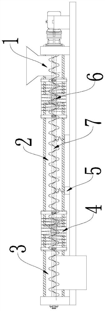
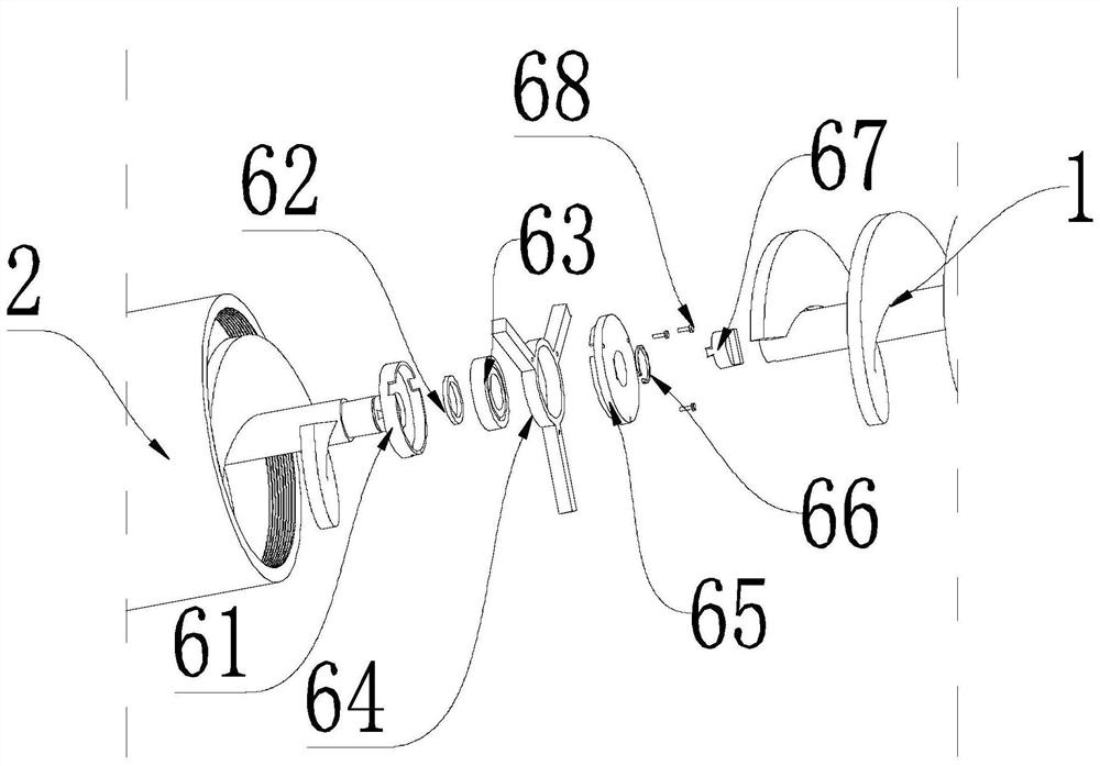
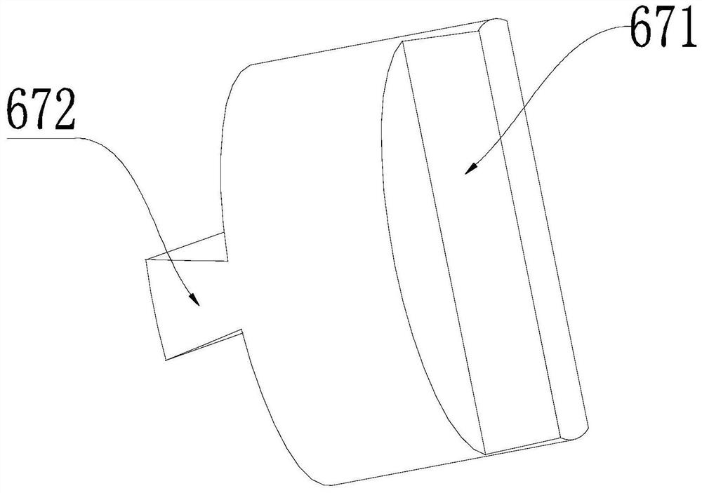
[0026] Example 1: See Figure 1 to Figure 3 , a multi-stage high-precision spiral cuttings weighing device of this embodiment, including a feed section 1, a weighing section 2 and a discharge section 3, the feed section 1 is used to receive the bottom of the well and pass through the vibrating screen The processed cuttings, the weighing section 2 is used to weigh the cuttings, the discharge section 3 is used to discharge the cuttings, and one end of the weighing section 2 is provided with a The first floating connection device 6, the other end is provided with the second floating connection device for connecting the discharge section 3; the floating connection device 6 includes a connecting block 67, and the first linear concave groove, the discharge section 3 is provided with a second linear groove, one side of the connecting block 67 is provided with a first fixing protrusion 672 for connecting with the first linear groove, and the other side is provided with There is a sec...

Embodiment 2

[0027] Example 2: See Figure 1 to Figure 3 , the cross-section of the first linear groove in this embodiment is a trapezoidal structure, the cross-section of the first fixing protrusion 672 is an inverted trapezoidal structure, and the first fixing protrusion 672 has a larger width. The side fits the first linear groove. Similar to the Oldham coupling, this structure is used to compensate for the different axis errors during installation and processing, as well as the deformation and displacement of each section of the screw during the working process of the device, so as to improve the coaxiality between the weighing section 2 screw and the shell. degree, thereby improving the measurement accuracy of the device, so that the screw shaft of the weighing section 2 will not be affected by the other two sections of the screw conveyor during the rotation process. The inverted trapezoid prevents the bumps and grooves from falling out. In this embodiment, the first fixing protrusi...

Embodiment 3

[0028] Example 3: See Figure 1 to Figure 3 , the floating connection device 6 of this embodiment also includes a snap spring 66, a stopper 62, a roller bearing 63, a support seat 64 and a protective shell arranged outside the connection block 67 in sequence, and the support seat 64 is provided with a A support rod connected with the outer cylinder, the protective shell is provided with a fixing hole through which the support rod passes. The number of support rods is three, and the angle between two adjacent support rods is 120°. The protective shell prevents impurities from entering the bearing and causing failure. The protective shell includes a first protective shell 61 and a second protective shell 65 which are detachably connected, and the first protective shell 61 and the second protective shell 65 are connected by screws 68 . The support seat 64 has threads on the outside for supporting on the outer cylinder, and the inside has holes for placing bearings, and its effect...


PUM


Abstract

The invention discloses a multi-section high-precision spiral rock debris weighing device and method. The multi-section high-precision spiral rock debris weighing device comprises a feeding section, a weighing section and a discharging section, the feeding section is used for receiving rock debris which flows out of the shaft bottom and is treated through a vibrating screen, the weighing section is used for weighing the rock debris, and the discharging section is used for discharging the rock debris; one end of the weighing section is provided with a first floating connecting device used for being connected with the feeding section, and the other end of the weighing section is provided with a second floating connecting device used for being connected with the discharging section; each floating connecting device comprises a connecting block, a first linear groove is formed in the feeding section, a second linear groove is formed in the discharging section, a first fixing protruding block used for being connected with the first linear groove is arranged at one side of the connecting block, a second fixing protruding block used for being connected with the second linear groove is arranged at the other side of the connecting block, and the first fixing protruding block and the second fixing protruding block are not parallel. No special technology is needed, the structure is simple, implementation is easy, and the rock debris weight measuring precision and the accuracy of judging the well bottom drilling condition are improved.

Description

technical field [0001] The invention relates to the technical field of petroleum drilling, in particular to a multi-stage high-precision spiral cuttings weighing device and method. Background technique [0002] In the process of oil drilling and shale gas development, as the burial depth increases, the geological engineering conditions become more complex, and complex accidents such as leakage, blowout, sticking, and collapse are prone to occur during the drilling stage, which increases the drilling cycle and drilling cost. The occurrence of complex accidents such as leakage, blowout, jamming, and collapse is often accompanied by changes in the amount of cuttings returned. Therefore, by monitoring the amount of cuttings returned in real time, the drilling status of the bottom hole can be accurately judged in a timely, accurate and low-cost manner. , take timely measures to reduce losses. The easiest way to monitor the change of cuttings returning and to measure and judge th...

Claims


Application Information

Patent Timeline
Patent Type & Authority Applications(China)
IPC IPC(8): G01G13/24G01G21/00G01G21/22
CPCG01G13/24G01G21/00G01G21/22
Inventor 姚建林郑凯中董仕明刘彬黄伟姚坤鹏余晟冯明周刚张伟陈文才孙雪梅
Owner CCDC PETROLEUM CORING TECH
Why Eureka
Try Eureka