Conductivity detection device for tungsten-zirconium electrode bar production

A detection device and electrode rod technology, which can be applied to measurement devices, measurement device casings, components of electrical measurement instruments, etc., can solve problems such as poor detection effect

Active Publication Date: 2021-12-28
深圳市北宸创新材料科技有限公司
View PDF4 Cites 0 Cited by
  • Summary
  • Abstract
  • Description
  • Claims
  • Application Information

AI Technical Summary

Problems solved by technology

[0004] In order to overcome the shortcomings of poor detection effect and manual collection of electrode rods, the technical problem is to provide a conductivity detection device for the production of tungsten-zirconium electrode rods, which has good detection effect of electrode rods and is convenient for collecting qualified electrode rods

Method used


Image

  • Conductivity detection device for tungsten-zirconium electrode bar production
  • Conductivity detection device for tungsten-zirconium electrode bar production
  • Conductivity detection device for tungsten-zirconium electrode bar production

Examples


Embodiment 1

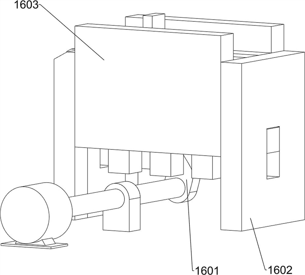
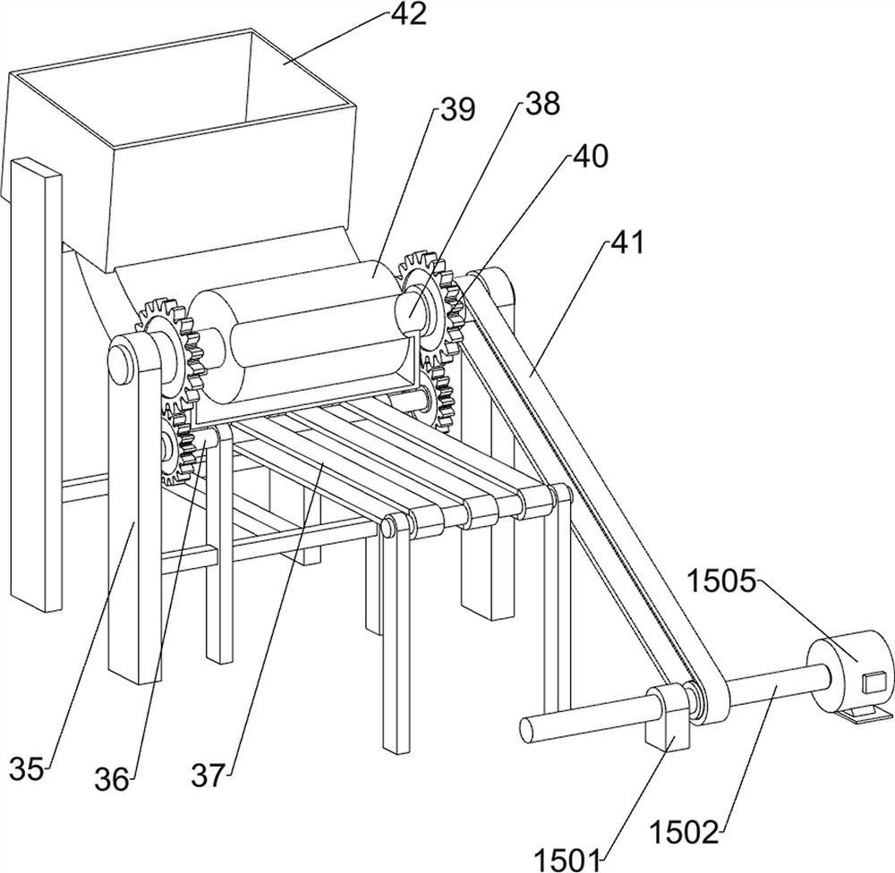
[0080] A conductivity detection device for the production of tungsten-zirconium electrode rods, such as figure 1 , figure 2 , image 3 with Figure 4 As shown, it includes a base 1, a first bracket 2, a first crawler belt 3, a placement table 4, an electrified metal block 5, a light bulb 6, a coil 7, an electric wire 8, a first baffle plate 9, a first guide block 10, a second Guide block 11, the first slider 12, the first elastic member 13, the first material box 14, the drive mechanism 15 and the fixing mechanism 16; The rotary type is provided with three rotating shafts, five first crawlers 3 are wound around the three rotating shafts, a placing platform 4 is arranged on the left rear side of the top of the base 1, and an electrified metal block 5 is arranged on the front side of the placing platform 4 top. 4. A light bulb 6 is arranged on the right side of the top, and a coil 7 is arranged on the left side of the top of the placing table 4. An electric wire 8 is connect...

Embodiment 2

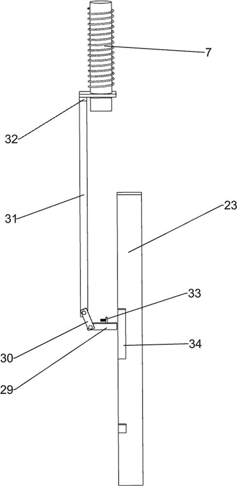
[0087] On the basis of Example 1, such as Figure 5 , Image 6 , Figure 7 , Figure 8 , Figure 9 with Figure 10 Shown, also comprise the 3rd bracket 17, the 3rd guide block 18, the first sliding bar 19, the first iron block 20, the second baffle plate 21 and guide bar 22, the first baffle plate 9 upper side and place table 4 front The third support 17 is provided on each side, and the third guide block 18 is arranged between the third support 17. The inner side of the left part of the third guide block 18 is slidably provided with a first sliding rod 19, and the rear side of the first sliding rod 19 is provided with The first iron block 20, the first iron block 20 cooperates with the coil 7, the middle part of the first sliding rod 19 is slidably provided with a guide rod 22, the middle part of the guide rod 22 is provided with a second baffle plate 21, and the second baffle plate 21 is placed on the third Slide in the guide block 18.

[0088] In the initial state, th...


PUM


Abstract

The invention relates to a detection device, in particular to a conductivity detection device for tungsten-zirconium electrode bar production. The technical problem is to provide the conductivity detection device for tungsten-zirconium electrode bar production, which has a good electrode bar detection effect and is convenient to collect qualified electrode bars. A conductivity detection device for tungsten-zirconium electrode bar production comprises: a base, wherein six first supports are arranged on the base, and a rotating shaft is rotationally arranged between every two adjacent first supports; first crawler belts, wherein five first crawler belts are wound between three rotating shafts; a placing table which is arranged on the base; an electrified metal block which is arranged on the placing table; a bulb which is arranged on the placing table; and a coil which is arranged on the placing table. Through cooperation of the electrified metal block, the bulb, the coil and the wire, the electrode bar is subjected to automatic conduction detection, and the use is relatively convenient.

Description

technical field [0001] The invention relates to a detection device, in particular to a conductivity detection device for production of tungsten-zirconium electrode rods. Background technique [0002] Before using the tungsten-zirconium electrode rod, people need to conduct a conductive test on it, and the qualified electrode rod can be used. The conductive test of the electrode rod requires people to use a detection device to detect it. First, people manually place the electrode rod to be tested on the detection device. On the device, people then manually manipulate the detection device to perform conductivity detection. The existing conductivity detection device does not fix the electrode rods enough, which makes the detection effect not good enough. The qualified electrode rods need to be removed manually, which is inconvenient. [0003] To sum up, in view of the above existing problems, a conductivity detection device for the production of tungsten-zirconium electrode rod...

Claims


Application Information

Patent Timeline
Patent Type & Authority Applications(China)
IPC IPC(8): G01R31/01G01R1/02G01R1/04B07C5/344
CPCG01R31/013G01R1/02G01R1/0408B07C5/344Y02E30/30
Inventor 陆孳桂
Owner 深圳市北宸创新材料科技有限公司
Why Eureka
Try Eureka