Ophthalmic lens

A spectacle lens and eye technology, applied in the field of spectacle lenses, can solve the problems of inability to reduce eye irritation and effectively inhibit the development of myopia, and achieve the effects of improving clarity, reducing eye fatigue, and reducing glare

Pending Publication Date: 2021-12-28
丹阳市雷登智能科技有限公司
View PDF3 Cites 1 Cited by
  • Summary
  • Abstract
  • Description
  • Claims
  • Application Information

AI Technical Summary

Problems solved by technology

However, because the second refraction area of ​​the above-mentioned spectacle lens is formed as a plurality of island-shaped areas independent of each other, all the light rays passing through the first refraction area will be concentrated and act on the patient's retina at the same time. Therefore, this Although spectacle lenses theoretically inhibit the development of myopia through the second refraction zone, they actually cannot reduce the stimulation and glare caused by the light passing through the first refraction zone to the eyes, causing eye fatigue (glare and eye fatigue are the causes of The main factor of myopia), therefore, still can not effectively inhibit the development of myopia

Method used


Image

  • Ophthalmic lens
  • Ophthalmic lens
  • Ophthalmic lens

Examples


Embodiment 1

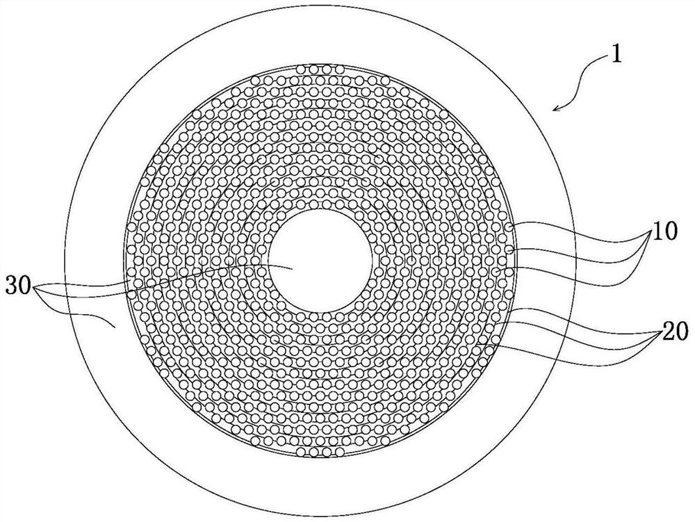
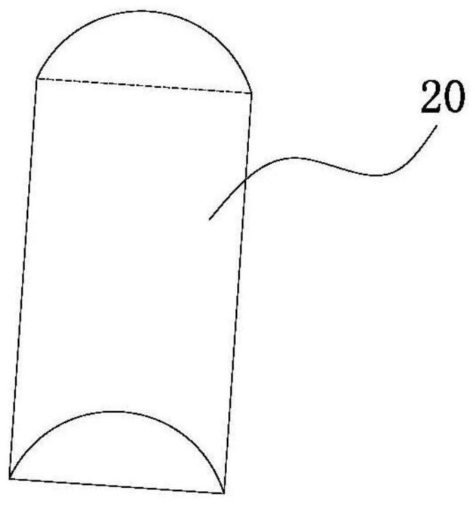
[0028] Such as figure 1 The spectacle lens 1 shown, the spectacle lens 1 is a concave lens having an object-side surface and an eye-side surface, wherein the object-side surface is formed as a convex curved surface toward the object side, and the eye-side surface is formed to have a curvature larger than that of the object-side surface concave. The spectacle lens 1 has a first unit 10 that focuses the image on a position other than the retina of the eye to inhibit the development of refractive error in the eye, a second unit 20 that diverts light from a straight line, and a plurality of third units 30 that correct myopia. The following are respectively Describe each part and the relationship between the parts in detail:

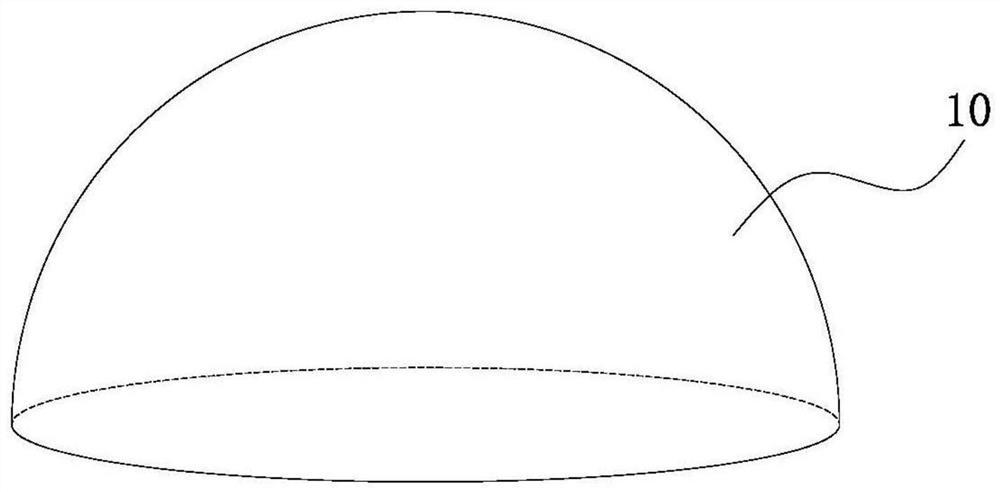
[0029] Such as figure 1 As shown, the first unit 10 is made of a material having a point to focus an image in front of the retina of the eye, and the second unit 20 and third unit 30 have the function of focusing the image on the retina of the eye. Therefo...

Embodiment 2

[0037] Such as Figure 4 with Figure 5, the plurality of first units 10 are respectively arranged at intervals on a plurality of rings with the same center to form the outermost suppression layer A, the innermost suppression layer B and at least one middle suppression layer C, these middle suppression layers C is located between the outermost suppression layer A and the innermost suppression layer B. The center of each first unit 10 in each layer of suppression layer is located on the same ring, that is, the center of each first unit 10 in the outermost layer of suppression layer A is located on the outermost ring, and the innermost layer suppresses Each first unit 10 in layer B is centered on the ring of the innermost layer, and each first unit 10 in the middle suppression layer C is centered on the ring of the middle layer. In the present invention, the number of intermediate suppression layers C is preferably three layers.

[0038] Such as Figure 4 with Figure 5 , e...


PUM


Abstract

The present invention discloses an ophthalmic lens. The ophthalmic lens comprises: a plurality of first units for focusing an image at a position other than the retina of the eye to suppress the development of refractive error of the eye, wherein the first units have a first diopter, further comprises: a second unit for propagating light deviating from a straight line, the plurality of first units being connected by the second unit; a plurality of third units for correcting myopia, wherein the third units are formed as regions other than those formed as the first units and the second units, the diopter of the second units and the diopter of the third units are different from the diopter of the first units, and light passing through the second units and the third units acts on the retina to form phase difference. The method has the advantage of inhibiting myopia development.

Description

technical field [0001] The invention relates to an ophthalmic lens. Background technique [0002] The frame glasses adopt single-focal concave lens, bifocal concave lens and progressive multi-focal lens, and the peripheral defocus frame glasses control the deepening of myopia. CN208921990U discloses a kind of eyeglasses and glasses that can control the increase of myopia, said eyeglasses include upper eyeglasses and lower eyeglasses, the diopter of eyeglasses is higher than the diopter of lower eyeglasses, and the said upper eyeglasses and lower eyeglasses are connected by respective connection surfaces , the adjacent side surfaces of the upper lens and the lower lens are respectively connected to smooth curved surfaces. The lenses and glasses can control the excessive growth of myopia. [0003] CN202339453U discloses a kind of special-purpose glasses for controlling myopia and reducing degrees, comprising a frame and lenses, the lenses are fixed on the frames, and the len...

Claims


Application Information

Patent Timeline
Patent Type & Authority Applications(China)
IPC IPC(8): G02C7/06
CPCG02C7/06G02C2202/24
Inventor 周民杰
Owner 丹阳市雷登智能科技有限公司
Why Eureka
Try Eureka