
Amphibious inspection robot

An inspection robot, amphibious technology, applied in the direction of manipulators, manufacturing tools, etc., can solve the problems of single inspection function and high operating environment requirements

Pending Publication Date: 2021-12-31
盐城中科高通量计算研究院有限公司
View PDF0 Cites 0 Cited by
  • Summary
  • Abstract
  • Description
  • Claims
  • Application Information

AI Technical Summary

Problems solved by technology

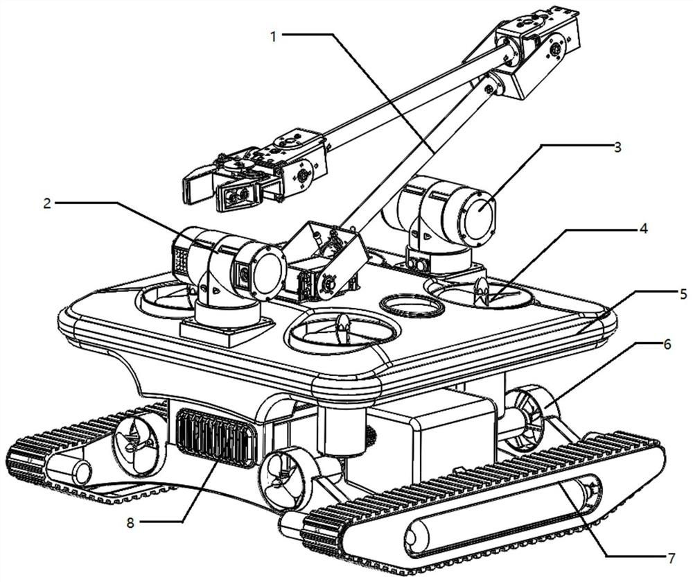
By setting the underframe at the bottom of the robot, installing track wheels on both sides of the underframe, and installing vertical propellers and horizontal propellers on the upper and middle parts of the underframe, the track wheels and propellers can realize the purpose that the robot can run on land and in water. The inspection device is installed before and after the protective shell installed on the robot. The inspection device is equipped with a rotating device, a searchlight and a camera to realize the full coverage of the rotating shooting and observation around the robot's operating range. When shooting in a dark place or underwater, the searchlight Provide lighting to meet the needs of shooting inspections; the top of the robot is equipped with a mechanical arm, and the front end of the robotic arm is equipped with a mechanical claw. Through the control and cooperation of the mechanical arm and the mechanical claw, it can discharge or collect samples from roadblocks that appear during the operation of the robot. Through reasonable design, it can realize amphibious use, remote control, and intelligent operation, and solve the shortcomings of the existing patrol inspection function, high requirements for the operating environment, and low intelligence.

Method used


Image

  • Amphibious inspection robot
  • Amphibious inspection robot
  • Amphibious inspection robot

Examples


Embodiment Construction

[0023] Below in conjunction with accompanying drawing and specific embodiment the present invention is described in further detail:

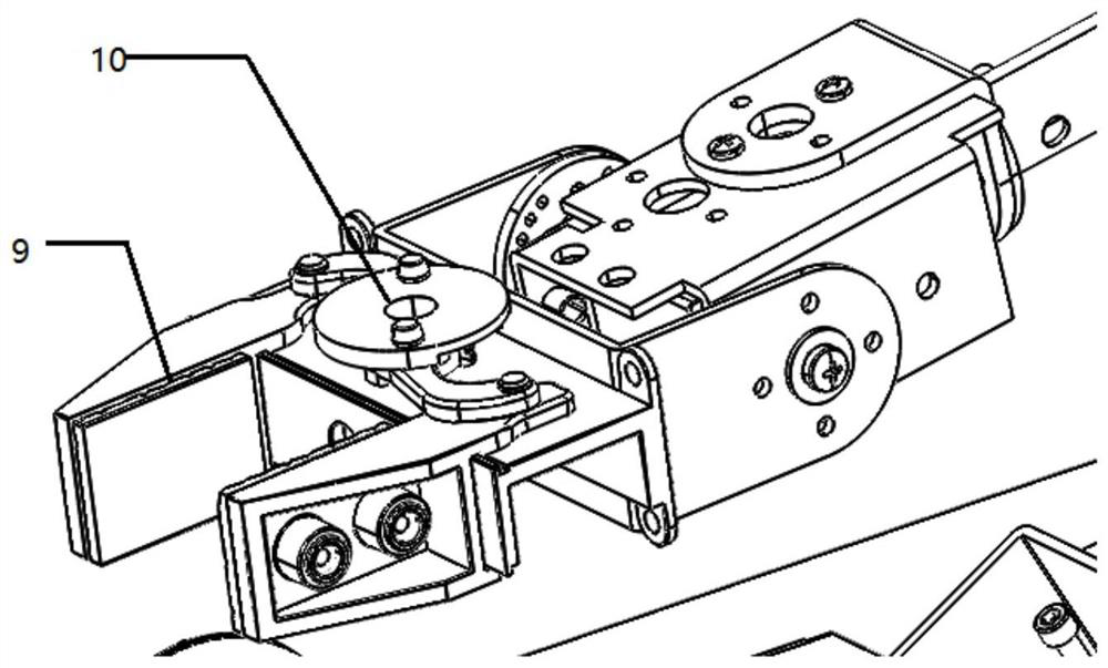
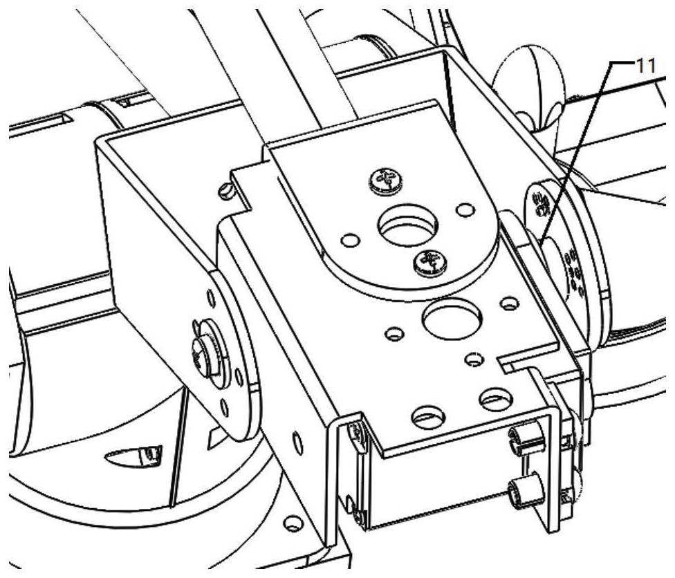
[0024] Such as Figure 1-6 As shown, an amphibious inspection robot provided by the present invention includes a mechanical arm 1, a front inspection device 2, a rear inspection device 3, a vertical propeller 4, a protective shell 5, a horizontal propeller 6, and a track wheel 7. Underframe 8, mechanical claw 9, rotating device 10, rotating device control motor 11, searchlight 12, base 13, rotating device 14, camera 15, crawler belt 16, crawler motor 17, protective box 18, crawler protection plate 19, beam 20. Motor one 21 and motor two 22, characterized in that: figure 1 The bottom of the shown amphibious inspection robot is provided with an underframe 8, the underframe 8 is a frame structure, and the underframe 8 is used as an equipment mounting frame for the robot. The structural spaces are designed according to the installation requirements...


PUM


Abstract

The invention relates to an amphibious inspection robot. The robot capable of running in water or on land for inspection is designed. Crawler wheels are arranged at the bottom of the robot and mounted on a bottom frame. A protective shell is mounted on the upper portion of the bottom frame. Propellers are mounted at the lower end and the top of the protective shell. Inspection devices are mounted in front of and behind the top of the protective shell. A mechanical arm is mounted in the middle of the top of the protective shell. The robot runs on land for inspection through the crawler wheels and runs in water for inspection through the propellers. The inspection devices mounted in front of and behind the protective shell shoot and record objects around the running route of the robot. When the front ends of the devices are hindered, objects hindering the front ends of the devices are treated through the mechanical arm, and normal running of the robot is guaranteed. Searchlights and high-definition cameras are mounted on the inspection devices. Bases of the inspection devices are rotatably arranged, and the surrounding conditions of the inspection robot can be shot and recorded. A protective box is arranged in the middle of the bottom frame. A controller, a main board and a power source for running of the robot are mounted in the box.

Description

technical field [0001] The invention belongs to the technical field of inspection robots, and in particular relates to the design and manufacture of an amphibious inspection robot. Background technique [0002] According to the needs of all walks of life, we all need to establish corresponding inspection management work, especially in petrochemical, communication, gas, electric power, railway, highway and other fields, it is necessary to conduct regular or irregular inspections to find hidden dangers and eliminate faults in time , to ensure the safety of equipment, pipelines, cables, and roads. In the past, people’s routine inspections were to arrange staff to conduct regular or irregular inspections on equipment implementation, road cables, etc., to ensure the normal operation of all walks of life. With the development of the times, more and more system industries need to be inspected. It is no longer practical to use personnel to inspect. Many places cannot be reached by p...

Claims


Application Information

Patent Timeline
Patent Type & Authority Applications(China)
IPC IPC(8): B25J5/00B25J11/00B25J19/00B25J19/06
CPCB25J5/00B25J5/005B25J11/00B25J19/00B25J19/06
Inventor 赵平平周晓宇陈传飞薛巨峰范东睿
Owner 盐城中科高通量计算研究院有限公司
Learn More