
Communication system and vehicle based on double-ECU joint control

A communication system and joint control technology, applied in the field of automotive communication, can solve problems such as inconsistent hardware design, different interface resistance settings, increased design and development costs, and management and use costs, so as to reduce use management costs and development costs Effect

Active Publication Date: 2021-12-31
CHINA FIRST AUTOMOBILE
View PDF9 Cites 2 Cited by
  • Summary
  • Abstract
  • Description
  • Claims
  • Application Information

AI Technical Summary

Problems solved by technology

[0003] In the existing dual-ECU joint control technology, in order to meet the resistance requirements of the CAN line for the connected ECU communication terminal, most of them do not choose the ECU as the terminal resistor, or connect the power CAN line as the ECU interface of the terminal and non-terminal resistors. Different resistance settings and inconsistent hardware design will increase design and development costs and management and use costs in different aspects

Method used


Image

  • Communication system and vehicle based on double-ECU joint control
  • Communication system and vehicle based on double-ECU joint control
  • Communication system and vehicle based on double-ECU joint control

Examples


Embodiment 1

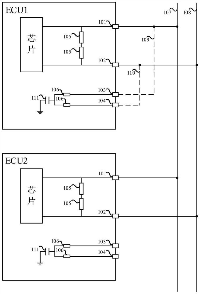
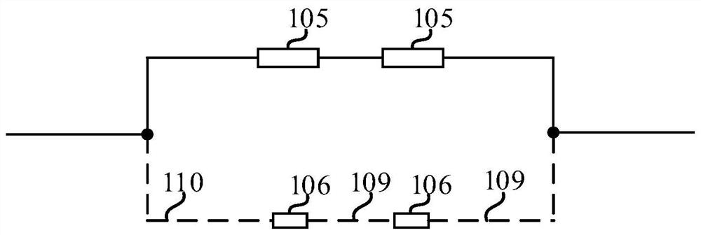
[0021] figure 1 It is the line connection diagram of the communication system based on dual ECU joint control provided by Embodiment 1 of the present invention, figure 2 It is a structural schematic diagram of the internal interface circuit of the ECU connected to the CAN line provided by Embodiment 1 of the present invention. Such as figure 1 with figure 2 As shown, the communication system includes: two electronic control units ECU, each ECU is connected to the power CAN line 100 ; one of the ECUs is used as a terminal resistor on the power CAN line 100 .

[0022] The ECU in this communication system comprises a first communication terminal 101, a second communication terminal 102, a third communication terminal 103, a fourth communication terminal 104, a first resistor 105 and a second resistor 106; the first resistor 105 is connected to the first communication Between the terminal 101 and the second communication terminal 102; the second resistor 106 is connected betw...

Embodiment 2

[0031] see figure 2 , optionally, in the embodiment of the present invention, when the ECU is used as a terminal resistor connected to the power CAN line, in addition to the first resistor that needs to be set between the first communication terminal 101 and the second communication terminal 102 of the normally connected communication interface 105 is connected to the power CAN line, and the second resistor 106 provided between the third communication terminal 103 and the fourth communication terminal 104 of the optional communication interface needs to be connected to the power CAN line through the first wiring harness 109 and the second wiring harness 110; When used as a non-terminal resistor connected to the power CAN line, it is only necessary to connect the first resistor 105 provided between the first communication end 101 and the second communication end 102 of the normally connected communication interface to the power CAN line. By setting the resistance values ​​of t...

Embodiment 3

[0035] Figure 4 It is the local area network diagram on the power CAN line in the vehicle topology provided by the embodiment of the present invention, such as Figure 4 As shown, the ECU1 with the terminal resistor 401 serves as the terminal resistor on the power CAN line 100 . ECU1 as a terminal resistor is the main ECU, and ECU2 connected to the power CAN line 100 as a non-terminal resistance is a slave ECU; text, and only ECU1 as the master ECU can send messages to the power CAN line 100, and the ECU1 as the master ECU can also be connected with the ECU2 as the slave ECU through the third line 402, and the third line 402 can be private The CAN line is used to realize the information communication between the specific master ECU and the slave ECU.

[0036] In addition, it should be noted that since the hardware design of the master and slave ECUs is completely consistent, which can meet the interchange requirements during assembly, it is necessary to identify the master ...


PUM


Abstract

The embodiment of the invention discloses a communication system and a vehicle based on joint control of double ECUs, and the system comprises the two ECUs, each ECU is connected to a power CAN line; wherein one ECU is used as a terminal resistor; the ECU comprises first, second, third and fourth communication terminals and first and second resistors; the first resistor is connected between the first communication terminal and the second communication terminal; the second resistor is connected between the third communication terminal and the fourth communication terminal; the first communication terminal and the second communication terminal are connected to a first line and a second line of the power CAN line; a third communication terminal of the ECU as a terminal resistor is connected between the first communication terminal and the first line through a first wire harness, and a fourth communication terminal is connected between the second communication terminal and the second line through a second wire harness. According to the system of the invention, by optimizing the ECU hardware design, joint control of double ECUs is realized, when one of the ECUs is used as a terminal resistor, the ECUs can be directly exchanged, and the requirement of connecting to a CAN line interface circuit resistor is met.

Description

technical field [0001] The embodiment of the present invention relates to the technical field of automobile communication, in particular to a communication system and a vehicle based on dual ECU joint control. Background technique [0002] At present, for large-displacement multi-cylinder engines with eight cylinders and above, a single ECU is rarely used to control the engine. The electronic control unit hardware controlled by a single ECU is relatively large in size, and the circuit board circuit load of the ECU hardware is also complicated. Therefore, dual-ECU joint control technology is often used, which can share the ECU platform with small engines, and it is not necessary to separately develop a dedicated ECU for large-displacement engines, which greatly saves development costs. [0003] In the existing dual-ECU joint control technology, in order to meet the resistance requirements of the CAN line for the connected ECU communication terminal, most of them do not choose...

Claims


Application Information

Patent Timeline
Patent Type & Authority Applications(China)
IPC IPC(8): B60R16/023B60R16/02
CPCB60R16/023B60R16/0207Y02P90/02
Inventor 李郑楠魏晓冬魏利崔健于忠磊申连勇陈辰栗江
Owner CHINA FIRST AUTOMOBILE
Learn More