Rope slow release mechanism

A rope and slow-release technology, which is applied in the direction of motor vehicles, space navigation equipment, space navigation vehicles, etc., can solve the problems of fast release speed, transfer of objects and astronaut injuries, etc., to achieve simple operation and controllable slow-release release speed , the effect of high fault tolerance

Pending Publication Date: 2021-12-31
HARBIN INST OF TECH +1
View PDF0 Cites 0 Cited by
  • Summary
  • Abstract
  • Description
  • Claims
  • Application Information

AI Technical Summary

Problems solved by technology

[0005] In order to solve the problem that the release speed is too fast due to the excessive load of the tool bag during the transfer process, it is easy to cause damage to the transferred items and astronauts, and there is a lack of a mechanism for slowly releasing the rope and adjusting its release speed

Method used


Image

  • Rope slow release mechanism
  • Rope slow release mechanism
  • Rope slow release mechanism

Examples


specific Embodiment approach 1

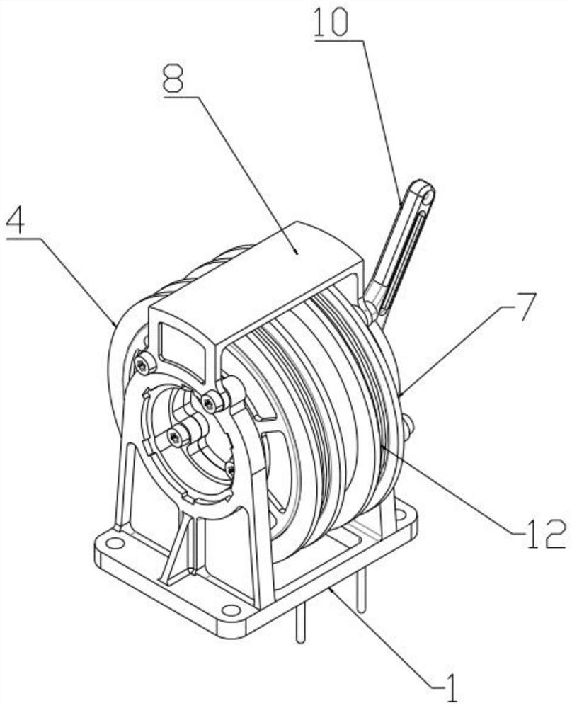
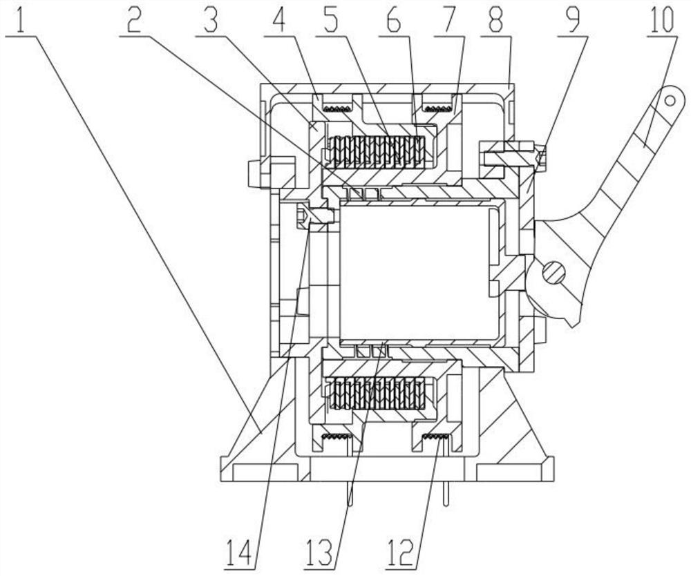
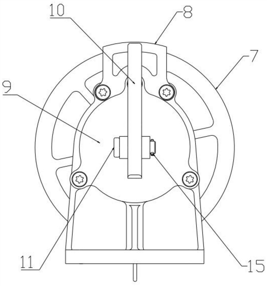
[0040] Specific implementation plan one: combine Figure 1 to Figure 12 As shown, the present invention provides a slow release mechanism for ropes, including a frame 1, a first sheave 4, a second sheave 7, an elastic shaft 2, an elastic shaft end cover 3, a slow release push sleeve 13, a friction Assembly and cam swing arm 10, the frame 1 is provided with an elastic shaft end cover 3 and an elastic shaft 2 connected by screws 14, the slow-release push sleeve 13 is built in the elastic shaft 2, and can be moved along the elastic shaft 2 Axial movement, the second sheave 7 is sleeved on the outside of the elastic shaft 2, the elastic shaft 2 is provided with a shoulder, the second sheave 7 is engaged with the shoulder, the elastic shaft end cover 3 and A friction assembly and a first sheave 4 are sequentially arranged between the second sheave 7, and the cam swing arm 10 is hinged with the frame 1 and is in contact with the slow-release push sleeve 13 for being pushed by the sw...

specific Embodiment approach 2

[0044] Specific implementation plan two: combine Figure 7 As shown, the elastic shaft 2 includes an integrally formed elastic shaft spring part 2-1 and an elastic shaft fixing part 2-2, and the elastic shaft spring part 2-1 is connected with the elastic shaft end cover 3 by screws 14. The elastic shaft fixing part 2 - 2 is connected with the frame 1 through screws 14 . By being provided with the elastic shaft spring part 2-1 and the elastic shaft fixing part 2-2, both can ensure that the elastic shaft 2 has elasticity, push the elastic shaft end cover 3, and then change the first sheave 4, the second sheave 7 and the friction Friction between components, adjust slow release rate. The other combinations and connections of this embodiment are the same as those of Embodiment 1.

specific Embodiment approach 3

[0045] Specific implementation plan three: combination Figure 1 to Figure 12 As shown, the elastic shaft end cover 3 , the friction assembly, the first sheave 4 and the second sheave 7 are pressed together in sequence, and in the initial state, the friction assembly is in a compressed state with friction. It is used to ensure the initial state and when the cam swing arm 10 is accidentally released, the elastic shaft 2 is in the initial state or automatically returns to the initial state, and the slow release mechanism is locked to prevent the tool bag or other items connected by the rope 12 from being released too quickly and damaged. The other combinations and connections of this embodiment are the same as those of the second embodiment.

[0046] Specific implementation plan four: combination Figure 8 to Figure 10 As shown, the friction assembly includes a plurality of inner friction plates 5 and a plurality of outer friction plates 6 , and the inner friction plates 5 and...


PUM


Abstract

The invention provides a rope slow release mechanism, and belongs to the technical field of toolkit transfer. The problems that due to the fact that the weight of a tool bag is too large, the releasing speed is too high, transferred objects and operators are prone to being hurt, and a mechanism for slowly releasing a rope and adjusting the releasing speed of the rope is lacked are solved. The mechanism comprises an elastic shaft end cover and an elastic shaft which are connected with each other are arranged in a rack, a slow release push sleeve is located in the elastic shaft, a second rope wheel is connected to the outer side of the elastic shaft in a sleeving mode, the second rope wheel is connected with the elastic shaft in a clamped mode, and a friction assembly and a first rope wheel are sequentially arranged between the elastic shaft end cover and the second rope wheel; a cam swing arm is connected with a frame; and the cam swing arm is contacted with the slow-release push sleeve. The elastic friction array with controllable prestress is arranged, accidental slippage can be avoided, displacement limiting is arranged, the error-tolerant rate is high, the structure is simple, the slow release speed can be adjusted by swinging the cam swing arm, operation is easy and convenient, the operation difficulty of astronauts can be effectively reduced, and the working efficiency is improved.

Description

technical field [0001] The invention relates to the technical field of tool bag transfer, in particular to a rope slow-release mechanism. Background technique [0002] During the inspection and exploration missions on the surface of the moon, the astronauts and detection tools need to be sent to the surface of the moon through the probe first, and the probe needs to carry a toolkit for the inspection and exploration tools, which generally includes cleaning the spacesuit. Brushes for collecting lunar dust, special hammers for smashing lunar surface rocks, shovels for digging lunar soil, rakes for picking up gravel on the lunar surface, sieves for sieving large-diameter lunar soil particles, spoons and pliers for lunar sample sampling And clips, and handles for carrying, etc., due to the relatively large weight and volume of the tool bag, in order to facilitate the astronauts’ operation and high safety, a tool bag transfer mechanism needs to be installed on the detector to rem...

Claims


Application Information

Patent Timeline
Patent Type & Authority Applications(China)
IPC IPC(8): B64G1/64B64G4/00
CPCB64G1/648B64G4/00
Inventor 姜生元鄢青青李建永成志忠王印超孙国鹏李林张伟伟叶耀坤苏小波马超蔺雪瑞
Owner HARBIN INST OF TECH
Why Eureka
Try Eureka