[0023] In order to more clearly explain the purposes of the present invention, the present invention will be further explained in conjunction with the accompanying drawings and examples. Embodiments, not all embodiments. Based on the embodiments of the present invention, all other embodiments obtained by those of ordinary skill in the art without paying creative labor, all of the scope of the present invention. Further, the direction term mentioned in the present invention, for example, "upper", "lower", "front", "left", "right", "inside", "outside", etc., is only reference The direction of the additional illustration is for better, more clearly, and understanding the invention, rather than indicating or having an indication of the present invention, and thus is not to be understood.
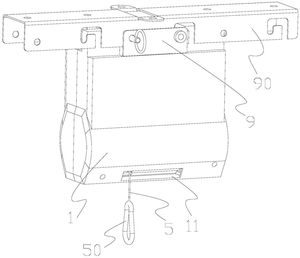
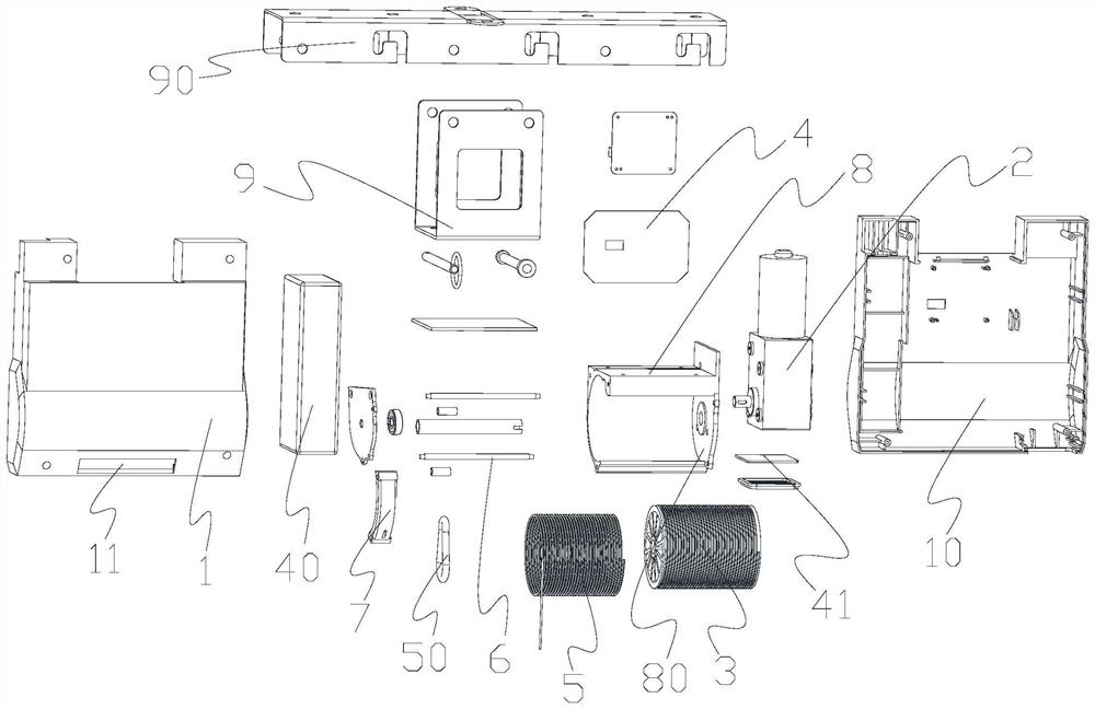
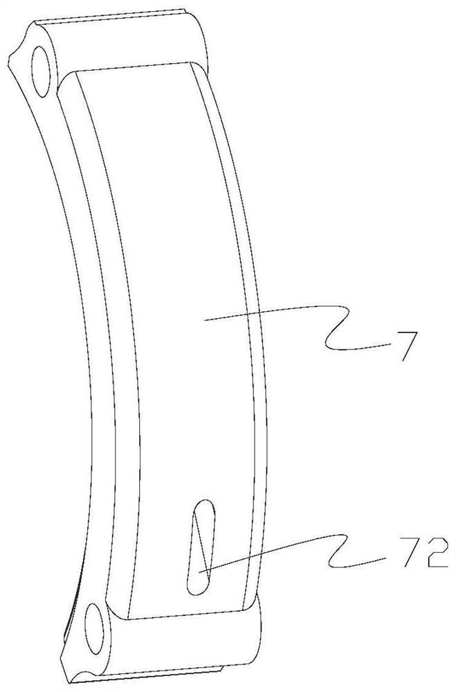
[0024] The invention is implemented, for example Figures 1 to 7As shown in a lifting device, comprising a housing accommodating the inner cavity 10 1, housed within a cavity 10 of the housing 1 to facilitate the installation of various components therein, to protect the components therein effect, the housing case 1 can be used integrated structure, and then mounting opening can be provided on the integrated structure, and for ease of installation, the housing comprises a front housing 1 engages is formed with a receiving cavity 10 and the rear housing, to facilitate the production and assembly, but also to facilitate the timely member within the housing 1 for maintenance replaced when problems arise, connected with a pivoting of the housing 2 by the reversible motor 10 is housed within the cavity the driving drum 3, i.e., the drum 3 can be rotated relative to the housing 1, which is rotatable in the receiving cavity 10, in this case the drum 3 within the housing 1 is pivotally connected to a rotating shaft is through achieved, the rotation shaft mounted in the housing 1, one end thereof connected to the housing 1 by a pivot bearing, and the other end is fixed to an output shaft connected to a reversible motor 2 while the drum 3 is provided on a rotating shaft sleeve is fixed, so that, bidirectional motor 2 is started, it would drive the output shaft rotational axis, the rotation axis of the drum 3 is rotated and driven, the housing 1 in the accommodating chamber 10 is also provided with a control circuit board 4, it is used to control the bidirectional motor 2 the operation of other electrical equipment, it means that the control circuit board 4 and the reversible motor or other electrical device 2 is electrically connected, while the wireless communication module may also be provided thereon, and a communication connection to the intelligent terminal via the wireless communication module or a remote and then for remote operation by remote control, or it can be performed on the intelligent terminal APP by respective remote control and monitoring of the lifting device, the cloud systems may be provided between the intelligent terminal and the apparatus, through the cloud the system more efficiently manipulate conveniently, while also provided with a metering control module, the metering module includes a reversible motor 2 count the number of times the counter reversing circuit board 4, the cable tension sensor 5 lifting weight of the product sensor, the counter circuit may be implemented using a counter to count through the reminder of the cable needs to be replaced after a certain number of times to use, to ensure safe use, the tension sensor for sensing the weight of the article lifting cables, to avoid overload lifting, while the display and alarm unit may also be provided outside the housing 1, the respective detected parameter display, so that people can understand intuitively that the lifting device is in any condition, to give warning when overload, avoiding the risk of occurrence; outer surface of the drum 3 is provided with a helical groove 30, 30 is satisfied that the contents of the spiral groove 5 can be retractable cable piercing end portion and an outer housing 1 with the rotary drum 3 helical groove 30 is used for accommodating the cable 5, i.e. 5 cable sling, which is mounted in the helical groove 30, with the spiral groove 30 to the outside of the drum 3 is wound, in which case the spiral grooves 30 depth of not less than the radius of the cable 5, a width no greater than the diameter of the cable 5, the cable 5 can be conveniently housed in the helical groove 30, when not in use, cables can 5 is pressed against the helical groove 30 , as the rotating drum 3, but also very convenient to use closed cable 5 Release, retaining the smoothness of 5 retractable cable, an outer cable housing 5 by piercing through holes 5 piercing the cable housing in the lower housing 1 is provided with a 11, a through hole 11 into housing strip length and the length of the drum 3 match, so that the cable 5 can be moved in the axial direction of the drum 3 in the same direction, to avoid the edge of the through hole 11 housing an adverse effect on cable; said housing 1 in the accommodating chamber 10 is also provided with axially with the drum 3 parallel guide rod 6, the sliding guide rods 6 is provided on the guide block 7, it determines the sliding direction of the guide block 7 and the cylinder 3 is the same axial direction, so that upon rotation of the guide rollers 3 to 7 to move axially in an outer wall of the drum 3, the arcuate guide block 7 is provided in the guide block and slide the outer wall of the drum 3, the arc of the guide pad 7 shaped to fit the shape of the outer wall of the drum 3, and 7 in order to ensure the sliding direction of the guide block, the guide rods 6 is provided with two parallel, both ends of the guide block 7 corresponding to the arcuate configuration of the slide provided on the two guide rods 6 in this case the guide block 7 is inferior arcuate guide block, the guide block 7 to facilitate mounting on the drum 3 and the outer wall of the slide, the guide block 7 is provided on the surface of the drum 3 in the axial direction corresponding to the intervals can helical groove 30 and can be engaged against the cable 5 is pressed against the first and second projection set of projections, the first projection set comprises a plurality of blocks along the guide 7 axially spaced first and the like arc-shaped protrusion 70, the second set of projections comprises a second plurality of arcuate axially along a guide pad 7 equally spaced projections 71, the guide block and the corresponding surface of the drum 3 is the inner surface 7, i.e., a first and second projection set of projections provided on both sides of the inner surface of the guide block 7, while the first projection group, the other side is a second group of projections, the projections in each group corresponding to contain a plurality of projections, the projections and the guide block 7 is matched with the guide projection piece 7 to the same arcuate configuration, the same spacing between each projection, each projection can snap into the corresponding cylinder 3 helical groove 30 of the outer wall, the cable 5 accommodated in the spiral groove 30 is pressed against or released to facilitate retractable cable 5, to ensure the smooth lifting of the guide block 7 and the second protrusion group adjacent first arcuate projection 70 provided at a position where the guide block through hole 72, both ends of the guide block through hole 7 arcuate structure 72 and the axis of the guide block parallel connection, that is to say the an axial through-hole 72 of the guide piece is a direction where the guide block 7 chord parallel, elliptical ports formed on both ends of the through-hole 72 of the guide block guide block 7, a cable guide block 5 from the through-hole 72 pass through the through-holes at both ends of the guide block 72, the cable 5 can be inconsistent on the pore walls of the through-hole 72 of the guide block, increases the contact area therebetween, as convenient cable guide block 5 7 is moved, but also to avoid damage to the sharp edges of the cable 5, the first arcuate protrusions 7 opposing the arcuate surface of the guide block 70 is a cross-sectional surface of the U-shaped structure into retraction, i.e. the first arc-shaped protrusion 70 is connected to the bottom surface of the guide pad 7 in the surface of the first arcuate protrusions of the top surface 70 and the guide block 7 that is opposite to a curved surface, which is facing the helical groove 30, the projection since the engagement groove 30 when the coil , Due to its U-shaped structure, there is a space therebetween, is housed in the helical groove 30 in the cable 5 is reduced in pressure applied thereto projection, can be very convenient activities in the space while a first plurality of arcuate protrusion 70 is disposed in parallel spaced, guide block 72 is provided in the through hole and a second position adjacent arcuate projections 71, so that, in use, a plurality of first arcuate protrusions 70 to treat the cable 5 is removed to release the pressure, to be moved the position where the guide block 72 to the through hole can be easily released from the helical groove 30, maintaining the smooth lifting, said second arcuate same projection 71 and the guide block 7 is a sectional opposing arcuate surface to the convex surface of the inverted U-shaped structure, in the same way the projection is engaged with the helical groove, due to the outwardly inverted U-shaped structure, to reduces the space distance between the two, the cable 5 accommodated in the spiral groove 30 on the protrusion by a pressure applied thereto, can be well accommodated in the helical groove 30, while the second arcuate protrusions 71 and a plurality of parallel spaced apart, so that, in use, a second plurality of arcuate projections 71 on the cable 5 accommodated treated sequentially pressed to ensure that the cable 5 can be housed in a complete helical groove 30 in favor of the next release, avoiding the generation of a retractable cable 5 in question Caton; the first arcuate protrusions of the first protrusion group and the spacing between the second set of projections 70 of the second arcuate protrusions 71 since the spacing between each projection and the spacing between the first and second group of the same projection.
[0025] Further improvement, such as Figure 1 to 6 As shown, the accommodating within the inner housing 3 pivot 8, the reversible motor 2 mounted in the inner shell 8, the set of inner housing 8 is attached to a lower portion of the inner cavity 10 of the housing 8, on the drum the drum 3 and the drum 3 in the helical groove 30 of the cable 5 is fixed in the inner case 8, to maintain the compactness and structural integrity, but also to avoid adversely affect each other, the shell 8 is provided with guide blocks within the matching case 7 slides the inner housing cutout 80, the two ends of the guide rod 7 is connected to the corresponding ends of the inner shell notch, the notch 80 of the inner shell 80 to facilitate driving the cable guide block 5 moves 7, while the rod guide 6 play a guide at the same time also play a role within the support housing 8, structural strength of the inner shell 8, the upper receiving cavity 10 is provided with a connector housing 8 and the inner top of the upwardly opening U-shaped bracket 9, the open end of the U-shaped bracket 9 and out through the top of housing 1 90 is connected to a mounting base, and a U-shaped mount bracket 9 is connected by a pin 90 to the mounting seat 90 for mounting the apparatus in the need to use place, the pin may be employed a pin fixed to the pin and activities with the use of the hook is set corresponding to the mount and through-hole 90, the first fixing pin hanging on the hook, and then through the other pin using the activity hook or vias to connect the U-shaped bracket and the mounting pad, easy accessibility, the control circuit board disposed in the U-bracket; the cable 5 passes through the inner shell 8 and the housing 1 and connected to an end hook 50, the hook 50 for hanging objects to be lifted, the hook 50 at this time can use a spring hook, easy to use.
[0026] Further improvement, such as figure 2 and Figure 5 As shown, the accommodating adapter is further provided with a power supply electrically connected to the control circuit board 4 inside the cavity 1040, easy to use, to ensure the safety and saving energy.
[0027] Further improvement, such as figure 2 and Figure 5 As shown, the accommodating chamber 10 is also provided within the control circuit board 4 is electrically connected to the LED 41, LED lamp 41 to facilitate use of the device under low-light conditions, which is disposed in the housing 1, a bottom surface, the bottom surface of the housing 1 is provided a through hole, the through-hole mounting the LED lamp, the LED lamp while the circuit board is formed in the integrated LED lamp board, but also to facilitate the production of easy to install.
[0028] It should be understood that in terms of one of ordinary skill in the art, it can be improved or transformed according to the above description, and all of these improvements and transformations should belong to the scope of the appended claims.