Check patentability & draft patents in minutes with Patsnap Eureka AI!

Continuous rigid frame track beam

A track beam and rigid structure technology, applied in bridges, bridge parts, bridge maintenance, etc., can solve problems such as line confusion, track beam offset, inconvenient maintenance, etc., and achieve the effect of improving stability

Pending Publication Date: 2021-12-31
任小强
View PDF8 Cites 0 Cited by
  • Summary
  • Abstract
  • Description
  • Claims
  • Application Information

AI Technical Summary

Problems solved by technology

[0004] The purpose of the present invention is to provide a continuous rigid track beam to solve the problems of inconvenient maintenance, slight deviation of the track beam and chaotic lines in the background technology

Method used


Image

  • Continuous rigid frame track beam
  • Continuous rigid frame track beam
  • Continuous rigid frame track beam

Examples


Embodiment Construction

[0029] The following will clearly and completely describe the technical solutions in the embodiments of the present invention with reference to the accompanying drawings in the embodiments of the present invention. Obviously, the described embodiments are only some, not all, embodiments of the present invention. Based on the embodiments of the present invention, all other embodiments obtained by persons of ordinary skill in the art without making creative efforts belong to the protection scope of the present invention.

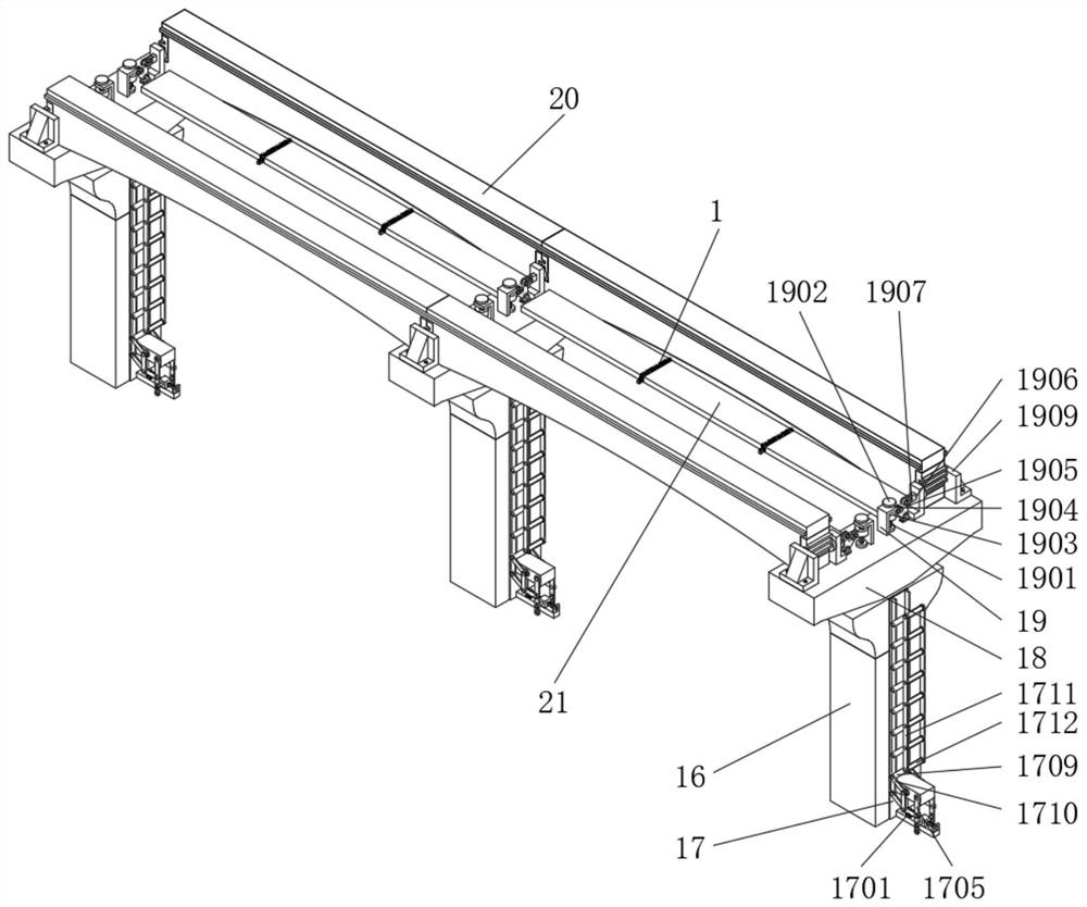
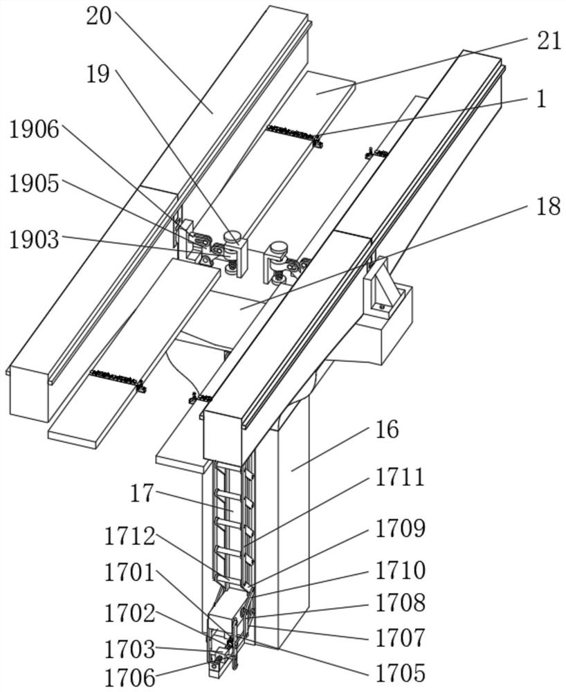
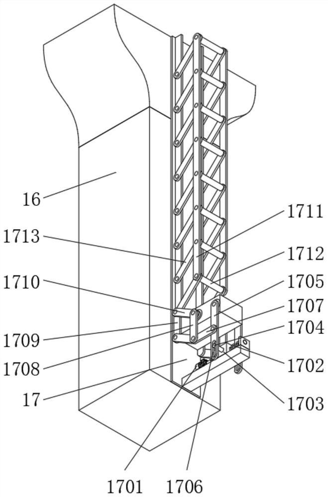
[0030] see Figure 1-8 , in an embodiment of the present invention, a continuous rigid frame track beam includes a wire harness frame 1, a right-angle bent plate 2, a telescopic rod 4, a telescopic hole box 6, a telescopic chute 8, a guide column 9, a lifting rod 10, a triangular rotary Plate 11, lifting pressure groove 13 and fixed pressure groove 14, the outer wall of the wire harness frame 1 is provided with a wrench 3 for driving the vertical rotation of t...


PUM


Abstract

The invention discloses a continuous rigid frame track beam, and relates to the technical field of continuous rigid frame track beams. The continuous rigid frame track beam comprises a bunching frame, a right-angle bending plate, a telescopic rod, telescopic hole boxes, a telescopic chute, a guide column, a lifting rod, a triangular rotating plate, a lifting pressing groove and a fixed pressing groove, the outer wall of the bunching frame is provided with a wrench used for driving the right-angle bending plate to vertically rotate; the section, away from the bunching frame, of the right-angle bent plate is movably connected with a telescopic hole plate used for driving the telescopic rod to stretch out and draw back horizontally, and the outer wall of the telescopic rod is fixedly connected with a telescopic spring used for driving the three sets of telescopic hole boxes distributed at equal intervals to stretch out and draw back synchronously. In the bunching frame, the wrench is rotated to drive the right-angle bent plate to rotate, so that the right-angle bent plate rotates to drive a telescopic rod to move through a telescopic hole plate, the telescopic rod moves to drive three groups of telescopic hole boxes to synchronously and oppositely move through the telescopic spring, and control operation on movement of a guide column is achieved.

Description

technical field [0001] The invention relates to the technical field of continuous rigid frame track beams, in particular to a continuous rigid frame track beam. Background technique [0002] The track beam is not only the track on which the monorail train travels, but also its load-bearing structure. At present, the general track beam structure system mainly includes simply supported system and continuous rigid frame system. In order to reduce the self-weight, the track beam of simply supported system at home and abroad is in the form of hollow section, while the continuous rigid frame system has no application engineering examples in China. , Foreign application projects all use hollow section track beams, and the variable height hollow section track beams put forward high requirements for the quality control of track beam construction. [0003] However, the existing continuous rigid frame track beam has the problem of inconvenient maintenance during use, which makes it im...

Claims


Application Information

Patent Timeline
IPC IPC(8): E01D19/00E01D22/00H02G3/04
CPCE01D19/00E01D22/00H02G3/04
Inventor 任小强刘晖陈正跃
Owner 任小强
Features
  • R&D
  • Intellectual Property
  • Life Sciences
  • Materials
  • Tech Scout
  • Unparalleled Data Quality
  • Higher Quality Content
  • 60% Fewer Hallucinations
Learn More