
Suspended ceiling module panel with lamp trough base frame

A technology of ceiling panels and base frames, which is applied in the direction of ceilings, building materials, building components, etc., can solve problems such as structural aging, bending deformation, and heavy loads of load-bearing plates, and achieve the effect of slowing down aging

Pending Publication Date: 2021-12-31
ZHEJIANG YASHA DECORATION
View PDF1 Cites 0 Cited by
  • Summary
  • Abstract
  • Description
  • Claims
  • Application Information

AI Technical Summary

Problems solved by technology

In this patent application, the wall plate of the insertion slot is spaced from the limiting plate to form the insertion slot, the wall plate of the auxiliary slot is spaced from the limiting plate to form the auxiliary slot, The splicing piece of the ceiling of the dark light trough inserts and splices the adjacent aluminum honeycomb panels through the insertion slot and the auxiliary slot. First, most of the weight of the honeycomb aluminum panel is borne by the load-bearing plate, which leads to a large load on the load-bearing plate and is prone to bending. Deformation, especially the part of the ceiling near the center is prone to downward deformation; secondly, the load-bearing plate and limit plate are prone to structural aging, bending and deformation after long-term use, resulting in The mouth becomes larger and the honeycomb aluminum plate becomes loose

Method used


Image

  • Suspended ceiling module panel with lamp trough base frame
  • Suspended ceiling module panel with lamp trough base frame
  • Suspended ceiling module panel with lamp trough base frame

Examples


Embodiment Construction

[0032] The present invention will be described in further detail below according to the accompanying drawings and examples of implementation.

[0033] The directional terms such as up, down, left, right, front, back, front, back, top, and bottom that are mentioned or may be mentioned in this specification are defined relative to the structures shown in the drawings. The words " "Inside" and "outside" respectively refer to the direction toward or away from the geometric center of a specific component. They are relative concepts, so they may change accordingly according to their different positions and different usage states. Accordingly, these or other directional terms should not be construed as limiting terms.

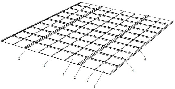
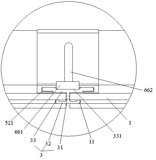
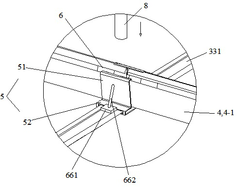
[0034] Refer to mention 1- Figure 12 , a ceiling assembly, comprising a plurality of ceiling boards 1 extending front and rear and arranged side by side, a plurality of lamp trough base frames 2 extending front and rear and splicing adjacent ceiling boards 1, a plur...


PUM


Abstract

The invention discloses a suspended ceiling module panel with a lamp trough base frame. The suspended ceiling module panel comprises at least two suspended ceiling plates and at least one lamp trough base frame, wherein the at least two suspended ceiling plates extend front and back and are arranged side by side left and right, and the at least one lamp trough base frame extends front and back and is spliced with the adjacent suspended ceiling plates; the lamp trough base frame comprises a bottom frame which is used for installing a lamp tube and a top frame which is erected on the bottom frame, lower supporting foot plates which are used for supporting the bottom faces of the suspended ceiling plates are arranged on the left and right sides of the bottom frame, and upper supporting foot plates which are pressed on the top faces of the suspended ceiling plates are arranged on the left and right sides of the top frame; and a plurality of tensioning mechanisms for connecting the bottom frame and the top frame are arranged between the bottom frame and the top frame at intervals in the front-back direction, and the tensioning mechanisms are used for applying acting force for opening the bottom frame and the top frame to the bottom frame and the top frame respectively, so that the suspended ceiling plates are clamped by the lower supporting foot plates and the upper supporting foot plates. The suspended ceiling module panel has the beneficial effect that the splicing firmness between the lamp trough base frame and the suspended ceiling plates can be improved.

Description

technical field [0001] The invention relates to a suspended ceiling module panel, in particular to a suspended ceiling module panel with a light groove base frame. Background technique [0002] Suspended ceiling refers to a kind of decoration on the top decoration of the living environment of the house. Simply put, it refers to the decoration of the ceiling, which is one of the important parts of interior decoration. [0003] In the prior art, for example, the publication number CN113417400A discloses a splicing piece for the suspended ceiling of the troffer. Including: main board, suspended ceiling installation board; suspended ceiling installation board, which is used to connect the main board with the roof; both sides of the main board are provided with insertion slots and auxiliary slots; the auxiliary slots are connected with the insertion slots; One side converges toward the ceiling mounting plate to form a light trough at the end of the main plate. In the prior art...

Claims


Application Information

Patent Timeline
Patent Type & Authority Applications(China)
IPC IPC(8): E04B9/00E04B9/22E04B9/28E04B9/16E04B9/18E04B1/38E04G21/14
CPCE04B9/006E04B9/22E04B9/28E04B9/16E04B9/18E04B1/38E04G21/14
Inventor 丁泽成王文广周东珊王聪聪蒋明哲
Owner ZHEJIANG YASHA DECORATION
Learn More