
Distance measuring device for electromechanical engineering construction and use method thereof

A technology of engineering construction and distance measuring device, which is applied to circuit devices, battery circuit devices, current collectors, etc., can solve the problems of inconvenient operation, poor flexibility of distance measuring devices, time-consuming and labor-intensive, etc.

Pending Publication Date: 2021-12-31
惠盟电力科技有限公司
View PDF0 Cites 0 Cited by
  • Summary
  • Abstract
  • Description
  • Claims
  • Application Information

AI Technical Summary

Problems solved by technology

[0003] The existing distance measuring devices used in mechanical and electrical engineering construction have poor flexibility. When in use, most of them are measured outdoors. Due to the complex outdoor terrain environment, it is difficult to ensure the horizontality of the device, which is inconvenient to operate and reduces the use effect. Secondly, the existing During the use of the distance measuring device used in electromechanical engineering construction, because it works outdoors, it needs to rely on its own power supply for power supply. When the power is insufficient, it cannot work and has poor practicability. In addition, the existing electromechanical engineering construction The mobility of the distance measuring device is poor. During use, the position needs to be adjusted continuously according to the needs of surveying and mapping. It requires staff to carry it, which is time-consuming and laborious. Therefore, a distance measuring device for mechanical and electrical engineering construction is urgently needed to solve the existing problems.

Method used


Image

  • Distance measuring device for electromechanical engineering construction and use method thereof
  • Distance measuring device for electromechanical engineering construction and use method thereof
  • Distance measuring device for electromechanical engineering construction and use method thereof

Examples


Embodiment Construction

[0033] The present invention will be further described below in conjunction with accompanying drawing:

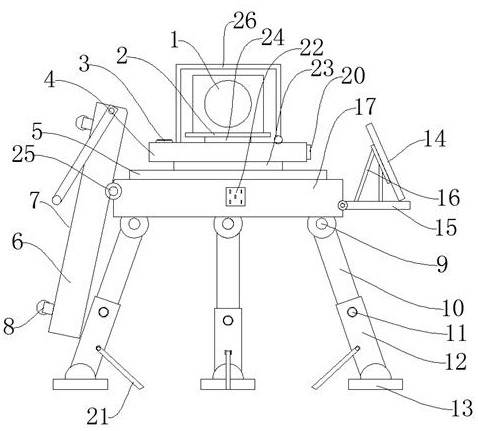
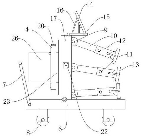
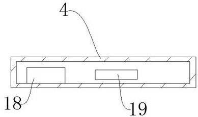
[0034] Such as Figure 1-Figure 4 As shown, a distance measuring device for mechanical and electrical engineering construction includes a machine base 17, a surveying instrument body 1 and a base 6, the upper end of the machine base 17 is provided with a shock absorbing plate 5, and the upper end of the shock absorbing plate 5 is provided with an electric motor. Push rod 23, the upper end of the electric push rod 23 is provided with a support seat 4, the side wall of the support seat 4 is provided with an operation panel 20, the upper end of the support seat 4 is provided with a rotating shaft 24, and the upper end of the rotating shaft 24 is provided with Support plate 2, the surveying instrument body 1 is arranged on the upper end of the support plate 2, and the surveying and mapping is carried out through the surveying instrument body 1, and the periphery of the surveyin...


PUM


Abstract

The invention discloses a distance measuring device for electromechanical engineering construction and a use method thereof. The distance measuring device comprises a base, a surveying instrument body and a base, wherein the upper end of the base is provided with a damping plate, and the upper end of the damping plate is provided with an electric push rod. The distance measuring device has the beneficial effects that the distance measuring device is novel in structure and convenient to operate, by arranging a gradienter, a leveling bottom plate, the electric push rod and a rotating shaft, a user can be helped to rapidly place the distance measuring device horizontally, surveying precision is guaranteed, in addition, the supporting plate can drive the distance measuring device to rotate through the rotating shaft to adjust the surveying direction, the height of the distance measuring device can be adjusted through the electric push rod, the flexibility of the distance measuring device is improved, operation is convenient, the using effect is improved, solar energy can be absorbed and converted into electric energy through a solar cell panel, a solar controller, a storage battery and a socket, the endurance of the distance measuring device is guaranteed, practicability is good, practicability is high, in addition, electronic equipment can be charged through the socket, and the functionality of the device is improved.

Description

technical field [0001] The invention relates to the technical field of distance measuring devices, in particular to a distance measuring device for mechanical and electrical engineering construction and a method for using the same. Background technique [0002] In the construction process of mechanical and electrical engineering, it is often necessary to measure distances, so distance measuring devices are needed. Measuring devices refer to the totality of measuring instruments and auxiliary equipment combined for measurement needs. It is often included in the list of commonly used measuring tools. [0003] The existing distance measuring devices used in mechanical and electrical engineering construction have poor flexibility. When in use, most of them are measured outdoors. Due to the complex outdoor terrain environment, it is difficult to ensure the horizontality of the device, which is inconvenient to operate and reduces the use effect. Secondly, the existing During the ...

Claims


Application Information

Patent Timeline
IPC IPC(8): F16M11/04F16M11/08F16M11/18F16M11/32F16M11/42H02J7/35H02J7/00H02S20/30
CPCF16M11/046F16M11/08F16M11/18F16M11/32F16M11/42H02J7/35H02J7/0042H02S20/30Y02E10/50
Inventor 许楷烽吴昊钟佰荣
Owner 惠盟电力科技有限公司
Learn More