
Near-infrared circularly polarized light imaging diffractive optical device

A technology of circularly polarized light and diffractive optics, applied in the field of diffractive optical devices for near-infrared circularly polarized light imaging, can solve the problems of restricting the practical application of polarization imaging, low efficiency, difficulty in integration and miniaturization

Pending Publication Date: 2021-12-31
PLA PEOPLES LIBERATION ARMY OF CHINA STRATEGIC SUPPORT FORCE AEROSPACE ENG UNIV
View PDF0 Cites 0 Cited by
  • Summary
  • Abstract
  • Description
  • Claims
  • Application Information

AI Technical Summary

Problems solved by technology

Since the sequential type is mainly aimed at static imaging; while the splitting type reduces the light energy reaching each pixel, resulting in low efficiency; and polarization splitting and focusing imaging require two optical elements, which is difficult to integrate and miniaturize, seriously restricting polarization Practical Applications of Imaging

Method used


Image

  • Near-infrared circularly polarized light imaging diffractive optical device
  • Near-infrared circularly polarized light imaging diffractive optical device
  • Near-infrared circularly polarized light imaging diffractive optical device

Examples


Embodiment Construction

[0049] Embodiments of the present invention will be described in detail below in conjunction with the accompanying drawings.

[0050] It should be noted that, in the case of no conflict, the following embodiments and the features in the embodiments can be combined with each other; and, based on the embodiments in the present disclosure, those of ordinary skill in the art obtained without creative work All other embodiments belong to the protection scope of the present disclosure.

[0051] It is noted that the following describes various aspects of the embodiments that are within the scope of the appended claims. It should be apparent that the aspects described herein may be embodied in a wide variety of forms and that any specific structure and / or function described herein is illustrative only. Based on the present disclosure one skilled in the art should appreciate that an aspect described herein may be implemented independently of any other aspects and that two or more of the...


PUM

PropertyMeasurementUnit
transmittivityaaaaaaaaaa
refractive indexaaaaaaaaaa

Abstract

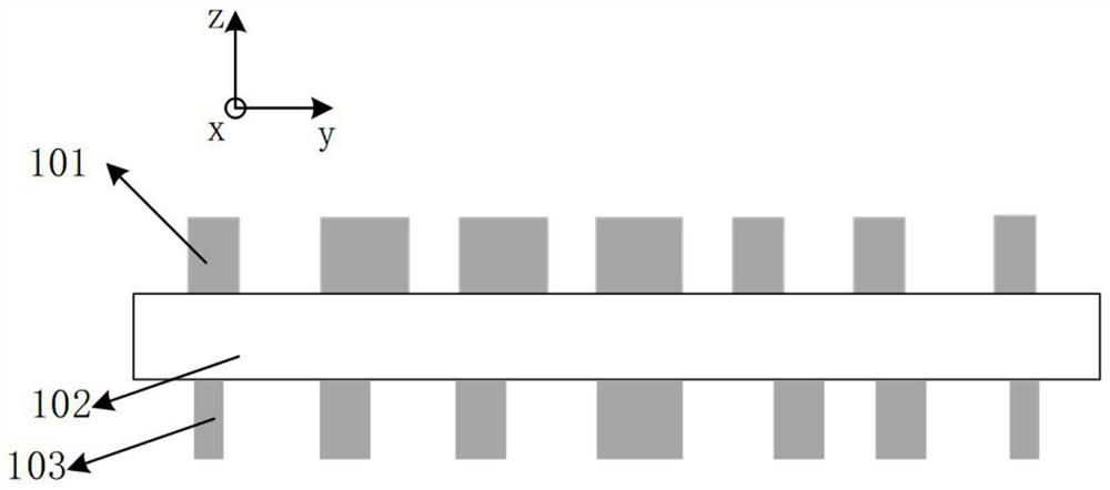
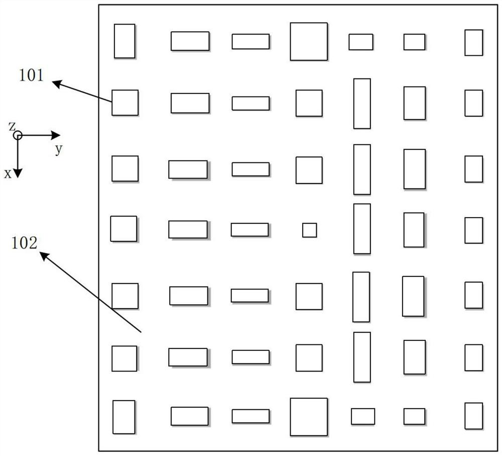
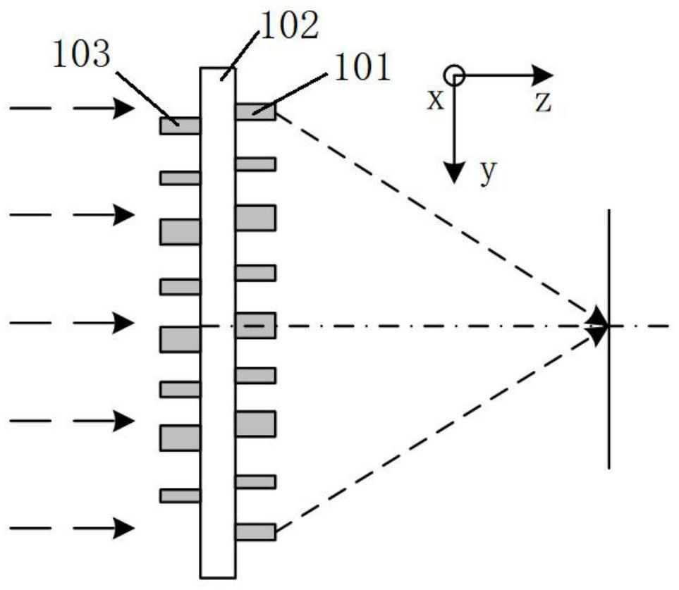
A near-infrared circularly polarized light imaging diffractive optical device provided by the invention comprises a substrate layer having a first surface and a second surface opposite to each other; multiple first sub-wavelength gratings which are arranged on the first surface of the substrate layer in an array mode; and multiple second sub-wavelength gratings which are arranged on the second surface of the substrate layer in an array mode. The size of each first sub-wavelength grating is determined by a first method, and the size of each second sub-wavelength grating is determined by a second method, so that the near-infrared circularly polarized light imaging diffractive optical device can apply a transmission phase to the circularly polarized light. According to the invention, the focusing imaging of the specific circularly polarized light is realized by using the double-layer metasurface, and the stray light is less.

Description

technical field [0001] The invention relates to the field of circularly polarized light imaging, in particular to a near-infrared circularly polarized light imaging diffractive optical device. Background technique [0002] Polarization is one of the fundamental properties of light. Substances will have different polarization characteristics due to their own properties (such as surface properties, roughness, shadow and shape, etc.) (the characteristic polarization determined by their own properties will be produced). Polarization imaging is the process of using the obtained information to reconstruct and enhance the target on the basis of real-time acquisition of target polarization information. Compared with techniques such as intensity imaging, spectral imaging, and infrared radiation imaging, in addition to obtaining traditional imaging information, it can Obtaining polarization information is a cutting-edge technology with great application value. It is especially suitab...

Claims


Application Information

Patent Timeline
Patent Type & Authority Applications(China)
IPC IPC(8): G02B5/18G02B5/30
CPCG02B5/1809G02B5/1838G02B5/3083
Inventor 赵峰姜明勇徐碧洁王昊月陈向宁
Owner PLA PEOPLES LIBERATION ARMY OF CHINA STRATEGIC SUPPORT FORCE AEROSPACE ENG UNIV
Learn More