Projection equipment and light source device thereof

A light source device and light spot technology, applied in projection devices, optics, instruments, etc., can solve the problems of space waste, excessive lens size, and overall large size of projection equipment, and achieve the effect of solving space waste and reducing the use of lens elements

Pending Publication Date: 2021-12-31
SHENZHEN HUOLE TECH DEV CO LTD
View PDF7 Cites 0 Cited by
  • Summary
  • Abstract
  • Description
  • Claims
  • Application Information

AI Technical Summary

Problems solved by technology

[0003] Embodiments of the present disclosure provide a projection device and its light source device, which can solve the technical problem in the prior art that the overall volume of the projection device is too large due to the excessively large lens size, resulting in a serious waste of space.

Method used


Image

  • Projection equipment and light source device thereof
  • Projection equipment and light source device thereof
  • Projection equipment and light source device thereof

Examples


Embodiment Construction

[0030] The following will clearly and completely describe the technical solutions in the embodiments of the present disclosure with reference to the accompanying drawings in the embodiments of the present disclosure. Apparently, the described embodiments are only some of the embodiments of the present disclosure, not all of them. Based on the embodiments in the present disclosure, all other embodiments obtained by those skilled in the art without creative efforts fall within the protection scope of the present disclosure. In addition, it should be understood that the specific embodiments described here are only used to illustrate and explain the present disclosure, and are not intended to limit the present disclosure. In the present disclosure, unless stated otherwise, the used orientation words such as "up" and "down" generally refer to up and down in the actual use or working state of the device, specifically the direction of the drawings in the drawings ; while "inside" and...


PUM


Abstract

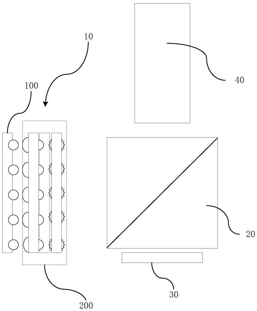
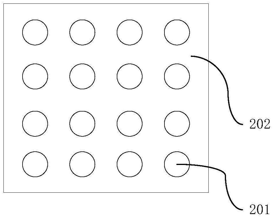
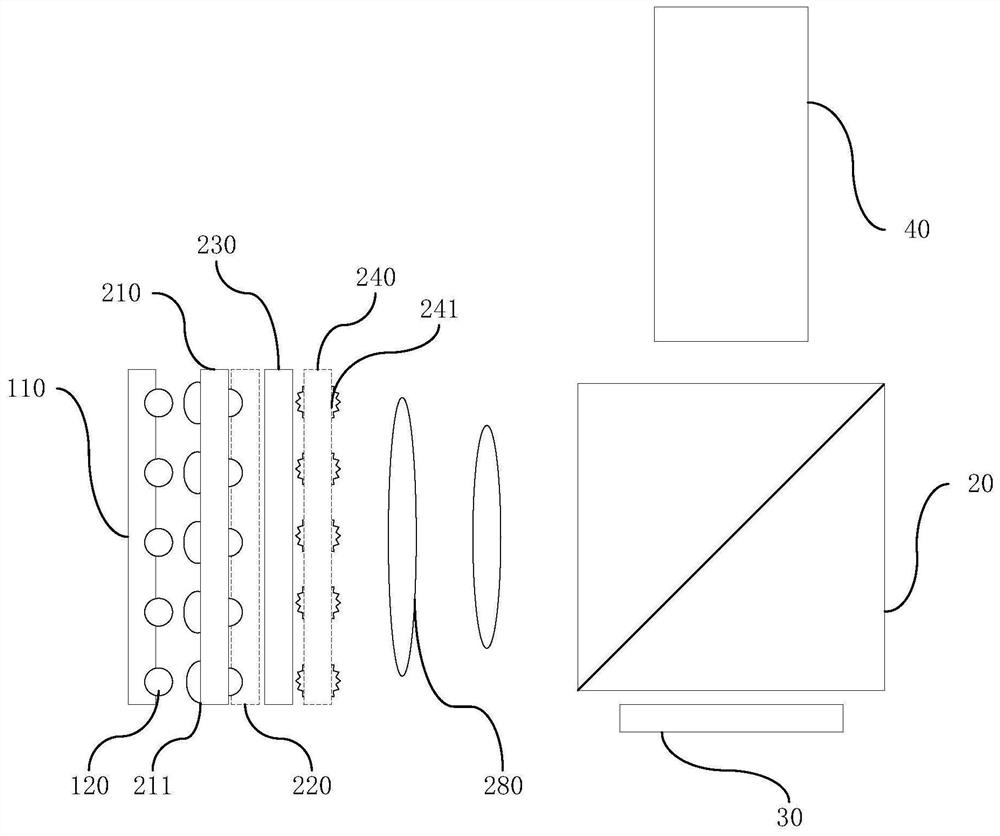
The embodiment of the invention discloses projection equipment and a light source device thereof. The light source device comprises a laser module and an optical array group. The laser module comprises a module carrier and a plurality of laser emitters, and the plurality of laser emitters are arranged on the module carrier in an array; the optical array group comprises a plurality of optical arrays and a plurality of light-transmitting layers which are sequentially arranged on one side of the laser module in the optical axis direction, each optical array comprises a plurality of optical units which are arranged along a plane array perpendicular to the optical axis, and the optical units are arranged corresponding to the laser emitters; and laser emitted by each laser emitter passes through the light-transmitting layer and the corresponding optical units. According to the invention, the plurality of optical arrays are arranged, each optical array comprises the plurality of optical units which are arranged along the plane array perpendicular to the optical axis, and the optical units are arranged corresponding to the laser emitters in the laser array, so that the use of large-size lens elements is reduced, therefore, the problem of space waste caused by overlarge size of the lens elements in the prior art is solved.

Description

technical field [0001] The present disclosure relates to the display field, in particular to a projection device and a light source device thereof. Background technique [0002] Many of the existing laser projection design ideas follow the traditional light bulb machine and LED light source projection design ideas. Therefore, the current laser projection scheme mainly uses traditional lenses to control the spot size and transmission angle of multiple laser beams. Under this projection scheme, in order to ensure the processing effect of the laser, the lens size and the laser spot size often differ by more than one order of magnitude, resulting in the overall volume of the projection equipment being too large, resulting in a serious waste of space. Contents of the invention [0003] Embodiments of the present disclosure provide a projection device and a light source device thereof, which can solve the technical problem in the prior art that the overall volume of the project...

Claims


Application Information

Patent Timeline
Patent Type & Authority Applications(China)
IPC IPC(8): G03B21/20
CPCG03B21/208G03B21/2033
Inventor 闫国枫张聪胡震宇
Owner SHENZHEN HUOLE TECH DEV CO LTD
Why Eureka
Try Eureka