Remote control method and control system

A remote control and control system technology, applied in the direction of image communication, selective content distribution, electrical components, etc., can solve the problems of taking more time, poor experience, and inconvenient use alternately, so as to increase convenience and intuitive effect

Pending Publication Date: 2021-12-31
AU OPTRONICS CORP
View PDF5 Cites 0 Cited by
  • Summary
  • Abstract
  • Description
  • Claims
  • Application Information

AI Technical Summary

Problems solved by technology

Therefore, when more peripheral devices are connected, there are more remote controllers, which is not very convenient for alternate use
In addition, in the field of smart terminal applications, the input interface options become more complicated, making consumers need to spend more time to operate
Although some solutions use bluetooth air mouse (air mouse), but because the control of air mouse belongs to the principle of relative coordinates, the experience in use is not good

Method used


Image

  • Remote control method and control system
  • Remote control method and control system
  • Remote control method and control system

Examples


Embodiment Construction

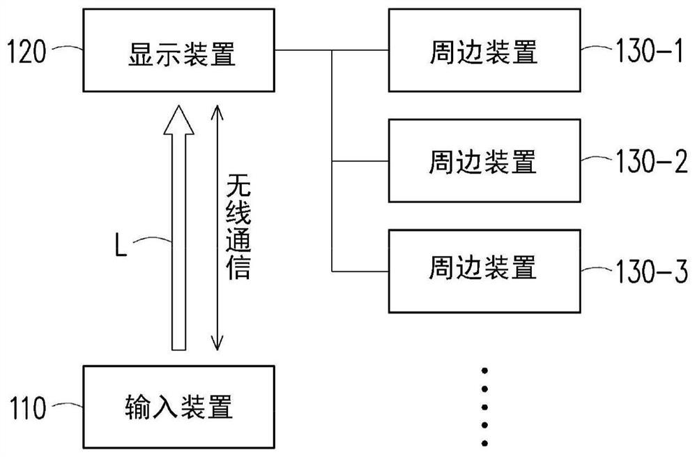
[0044] figure 1 is a block diagram of a control system according to an embodiment of the present invention. Please refer to figure 1 , the control system includes an input device 110 and a display device 120 . The display device 120 is coupled to peripheral devices 130-1˜130-3. Here, the number of peripheral devices is only for illustration and is not limited thereto. The detailed process of using the input device 110 together with the display device 120 to remotely control the peripheral devices 130 - 1 - 130 - 3 is described below with an example.

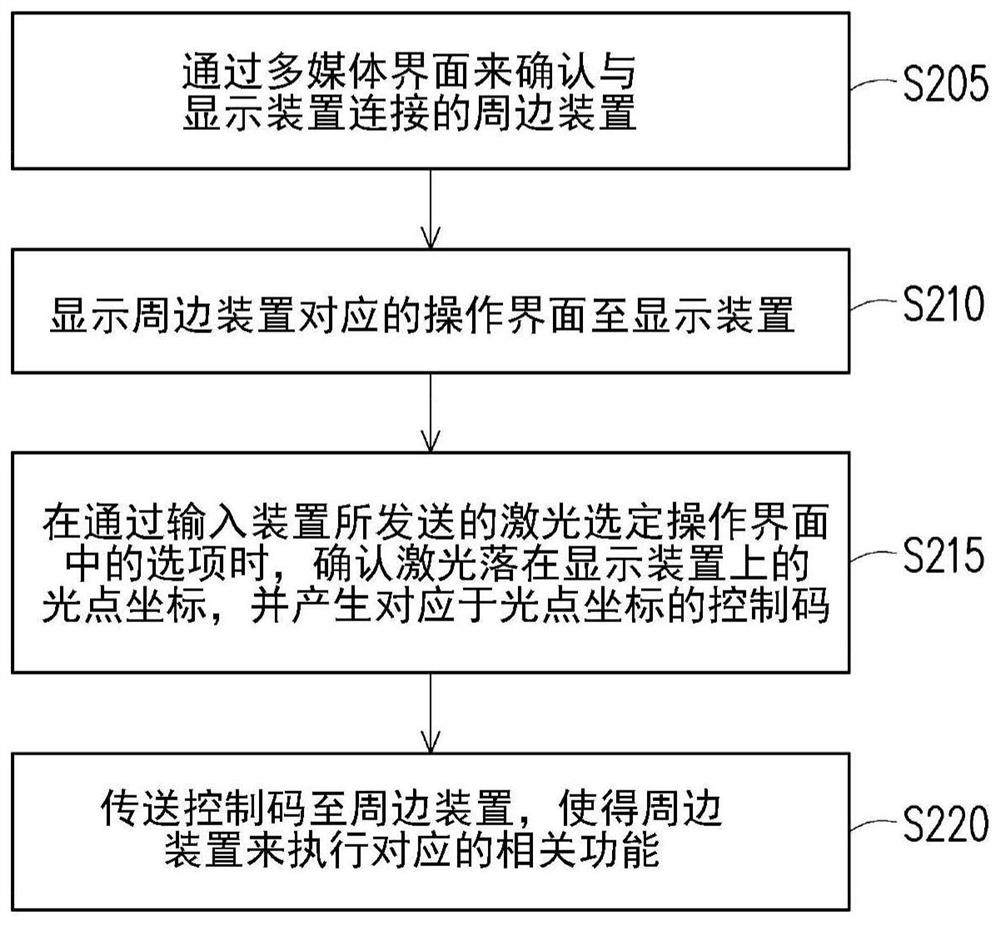
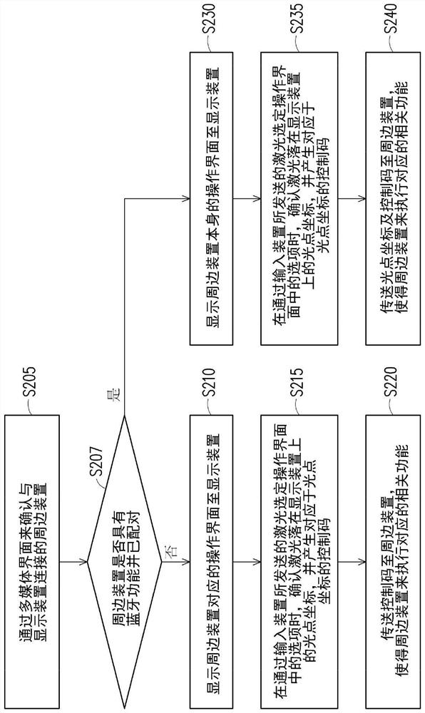
[0045] Figure 2A is a flowchart of a remote control method according to an embodiment of the present invention. image 3 It is a schematic diagram of realizing remote control according to an embodiment of the present invention. In this embodiment, the signal source of the display device 120 is switched to the peripheral device 130-1.

[0046] Please refer to Figure 2A and image 3 , in step S205, the display device 120...


PUM


Abstract

The invention discloses a remote control method and a control system. Firstly, a peripheral device connected to a display device is confirmed through a multimedia interface; then an operation interface corresponding to the peripheral device is displayed to the display device; moreover, when an option in the operation interface is selected through the laser emitted by the input device, light spot coordinates of the laser falling on the display device are confirmed, and a control code corresponding to the light spot coordinates is generated. Afterwards, the control code is transmitted to the peripheral device, so that the peripheral device executes the corresponding related function.

Description

technical field [0001] The present invention relates to a remote control mechanism, and in particular to a remote control method and control system. Background technique [0002] With the development of technology, TVs can be connected with more and more peripheral devices. At present, after the peripheral devices on the market are connected to the TV through, for example, a High Definition Multimedia Interface (HDMI), most of them use their corresponding dedicated remote controls to control them. Therefore, when more peripheral devices are connected, there are more remote controllers, which is not very convenient for alternate use. In addition, in the field of smart terminal applications, the input interface options become more complicated, making consumers need to spend more time on operations. Although some solutions use a Bluetooth air mouse (air mouse), the control of the air mouse is based on the principle of relative coordinates, which results in a poor user experie...

Claims


Application Information

Patent Timeline
Patent Type & Authority Applications(China)
IPC IPC(8): H04N21/422H04N21/431H04N21/436
CPCH04N21/42221H04N21/4312H04N21/436
Inventor 梁立明赖俊宏余祐东
Owner AU OPTRONICS CORP
Why Eureka
Try Eureka