Mold positioning device and die

A positioning device and mold technology, applied in the field of processing equipment, can solve problems such as damage to manipulators

Pending Publication Date: 2022-01-04
GOERTEK INC
View PDF0 Cites 0 Cited by
  • Summary
  • Abstract
  • Description
  • Claims
  • Application Information

AI Technical Summary

Problems solved by technology

[0005] The purpose of the present invention is to at least solve the problem in the prior art that th

Method used


Image

  • Mold positioning device and die
  • Mold positioning device and die
  • Mold positioning device and die

Examples


Embodiment Construction

[0050] Exemplary embodiments of the present disclosure will be described in more detail below with reference to the accompanying drawings. Although exemplary embodiments of the present disclosure are shown in the drawings, it should be understood that the present disclosure may be embodied in various forms and should not be limited by the embodiments set forth herein. Rather, these embodiments are provided for more thorough understanding of the present disclosure and to fully convey the scope of the present disclosure to those skilled in the art.

[0051] It should be understood that the terminology used herein is for the purpose of describing particular example embodiments only and is not intended to be limiting. As used herein, the singular forms "a", "an" and "the" may also be meant to include the plural forms unless the context clearly dictates otherwise. The terms "comprising", "comprising", "containing" and "having" are inclusive and thus indicate the presence of stated...


PUM


Abstract

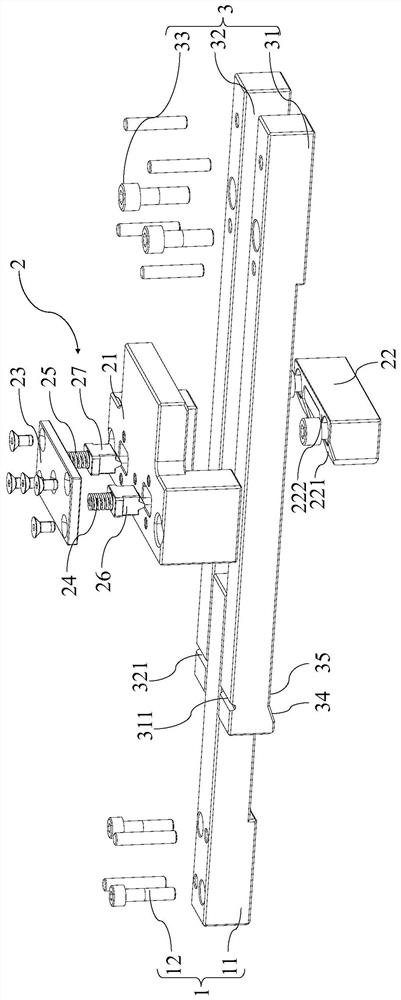
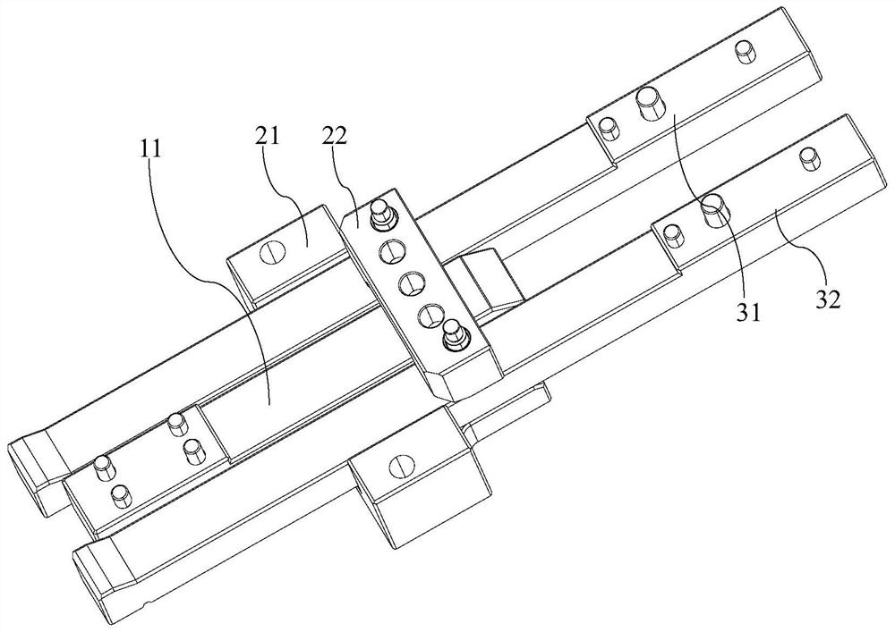
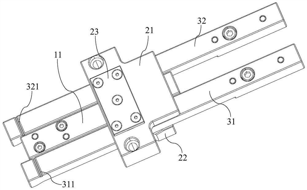
The invention belongs to the technical field of machining equipment, and particularly relates to a mold positioning device and a mold. The mold positioning device comprises a male mold fixing module, a female mold fixing module and a female mold fixing plate fixing module, the male mold fixing module is used for being connected with a male mold, and the female mold fixing module is used for being connected with a female mold; and the female mold fixing plate fixing module is used for being connected with a female mold fixing plate, the male mold fixing module is in contact connection with the female mold fixing module, and the female mold fixing module is arranged to be switched between a limiting state and a sliding state. According to the mold positioning device disclosed by the embodiment of the invention, the female mold fixing module and the female mold fixing plate fixing module are in limiting fit, so that product damage caused by the fact that a female mold rebounds to steal a main parting surface is avoided, and the quality of an injection product is ensured. Besides, the position of the female mold relative to a shifting plate is fixed, so that the gap between the female mold and the shifting plate is not changed, a manipulator can accurately enter the space between the female mold and the shifting plate to take out a rake, and the manipulator cannot be damaged due to interference.

Description

technical field [0001] The invention belongs to the technical field of processing equipment, and in particular relates to a mold positioning device and a mold. Background technique [0002] This document provides background information related to the present disclosure only and is not necessarily prior art. [0003] With the increasing prosperity of social and economic development, people's demand for the quality of various electronic products is getting higher and higher. In order to meet people's needs for various functions of electronic products, the product structure is becoming more and more complex, and more and more wearable electronic products The waterproof level requirements are high and the product size tends to be miniaturized and lightweight. However, the product structure space is limited, so it is necessary to use two-color product molding and then assemble it with buckles and glue to avoid the secondary yield reduction caused by the post-process assembly, re...

Claims


Application Information

Patent Timeline
IPC IPC(8): B29C45/66B29C45/44B29C33/30B29C45/80B29C45/26
CPCB29C45/66B29C45/44B29C33/308B29C45/2606B29C33/303
Inventor 张佳立赵永露杨吉龙孙桂明张芸农耀景
Owner GOERTEK INC
Why Eureka
Try Eureka