A kind of drainage pipe testing equipment
What is Al technical title?
Al technical title is built by PatSnap Al team. It summarizes the technical point description of the patent document.
A technology for detection equipment and drainage pipes, applied in the direction of detecting the appearance of fluid at the leakage point, measuring device, fluid tightness test, etc., can solve the problem of inability to detect pipes with different diameters, cannot intuitively find pipeline leaks, and increase detection Time and other issues
Active Publication Date: 2022-05-27
温州中陆水务科技有限公司
View PDF8 Cites 0 Cited by
Summary
Abstract
Description
Claims
Application Information
AI Technical Summary
This helps you quickly interpret patents by identifying the three key elements:
Problems solved by technology
Method used
Benefits of technology
Problems solved by technology
[0005] The purpose of the present invention is to provide a drainage pipeline detection device to solve the problems in the above-mentioned background technology that pipelines with different diameters cannot be detected and the location of pipeline leaks cannot be found directly manually, which increases the detection time.
Method used
Image
Click on the blue label to locate the original text in one second.
Reading with bidirectional positioning of images and text.
Examples
Embodiment Construction
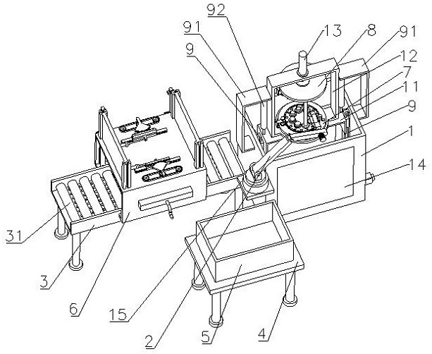
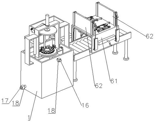
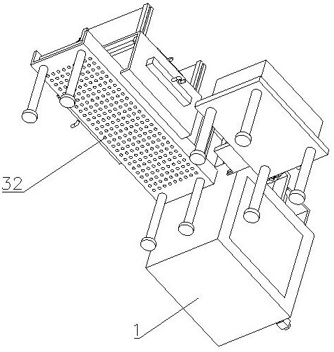
[0034] The present invention will be described in detail below, and the technical solutions in the embodiments of the present invention will be described clearly and completely. Obviously, the described embodiments are only a part of the embodiments of the present invention, rather than all the embodiments. Based on the embodiments of the present invention, all other embodiments obtained by those of ordinary skill in the art without creative efforts shall fall within the protection scope of the present invention.
[0035] The present invention provides a drainage pipeline detection device through improvement, such as Figure 1-Figure 10 As shown, it includes a detection tank 1, a lifting frame 11, a detection frame 12, a first hydraulic push rod 13, a manipulator 2, a conveying frame 3, a placing frame 4, a defective product box 5, a water removal component 6, and a first sealing component 7. , the second sealing assembly 8, the two guide rails 9, the two fixing frames 91 and ...
PUM
Abstract
The invention relates to the technical field of pipeline detection, in particular to a drainage pipeline detection equipment, including a detection water tank, a lifting frame, a detection frame, a first hydraulic push rod, a manipulator, a conveying frame, a placement frame, a defective product box, a water removal component, The first sealing assembly, the second sealing assembly, two guide rails, two fixing frames and two second hydraulic push rods, a transparent glass plate is arranged on the front outer wall of the detection water tank, and a mounting plate is installed on the left outer wall of the detection water tank. The lifting frame is slidably installed on the two guide rails, the detection frame is installed on the top of the lifting frame, the first hydraulic push rod is vertically arranged on the top of the detection frame, and the first sealing assembly and the second sealing assembly are respectively arranged on the top of the detection frame. On the top and the output end of the first hydraulic push rod, the dewatering assembly is installed on the top of the conveying frame. The invention realizes sealing detection for drainage pipes with different diameters, a large number of air bubbles are generated at the leakage points of the drainage pipes, which is convenient for manually visually finding the positions of the leakage points of the pipelines, and reduces the detection time.
Description
technical field [0001] The invention relates to the technical field of pipeline detection, in particular to a drainage pipeline detection device. Background technique [0002] Water Supply and Drainage (Water Supply and Drainage) is one of the engineering disciplines, referred to as water supply and drainage. Water supply and drainage science and engineering generally refers to the urban water supply system and drainage system (municipal water supply and drainage and building water supply and drainage), referred to as water supply and drainage. Water supply and drainage engineering studies the problem of a social cycle of water. "Water supply": a modern water plant, after extracting natural water from rivers and lakes every day, uses a series of physical and chemical means to purify the water into tap water that meets the standards of production and living water, and then passes through the urban water network extending in all directions. Tap water is delivered to thousand...
Claims
Application Information
Patent Timeline
Application Date:The date an application was filed.
Publication Date:The date a patent or application was officially published.
First Publication Date:The earliest publication date of a patent with the same application number.
Issue Date:Publication date of the patent grant document.
PCT Entry Date:The Entry date of PCT National Phase.
Estimated Expiry Date:The statutory expiry date of a patent right according to the Patent Law, and it is the longest term of protection that the patent right can achieve without the termination of the patent right due to other reasons(Term extension factor has been taken into account ).
Invalid Date:Actual expiry date is based on effective date or publication date of legal transaction data of invalid patent.