High-precision measuring device and method for dynamic displacement of structural micro-crack

A technology of dynamic displacement and measuring device, applied in electromagnetic measuring device, electric/magnetic solid deformation measurement, complex mathematical operation, etc., can solve problems such as damage, difficulty in measuring the dynamic change of micro-crack displacement, discount of test effect, etc. The effect of precision

Pending Publication Date: 2022-01-07
CHINA INST OF WATER RESOURCES & HYDROPOWER RES +1
View PDF6 Cites 0 Cited by
  • Summary
  • Abstract
  • Description
  • Claims
  • Application Information

AI Technical Summary

Problems solved by technology

However, the strain gauge will fail after the microcracks in the model structure are generated, and a series of dynamic evolution processes such as subsequent evolution, expansion change, and opening and closing changes after the microcracks cannot continue to be measured.
It is precisely because it is very difficult to measure the dynamic changes of micro-crack displacement that the shaking table tests of most model structures have not monitored the key process after micro-crack cracking-and this process is the most critical and can reveal the nonlinearity of geotechnical structure models. The test process of the characteristics of the destruction process makes this kind of test data unable to fully reveal the structural damage characteristics, and also greatly reduces the test effect
This has also become a bottleneck in the study of model structure shaking table failure tests.

Method used


Image

  • High-precision measuring device and method for dynamic displacement of structural micro-crack
  • High-precision measuring device and method for dynamic displacement of structural micro-crack
  • High-precision measuring device and method for dynamic displacement of structural micro-crack

Examples


Embodiment Construction

[0034] In order to make the object, technical solution and advantages of the present invention clearer, the present invention will be further described in detail below in conjunction with the accompanying drawings and embodiments. It should be understood that the specific embodiments described here are only used to explain the present invention, not to limit the present invention.

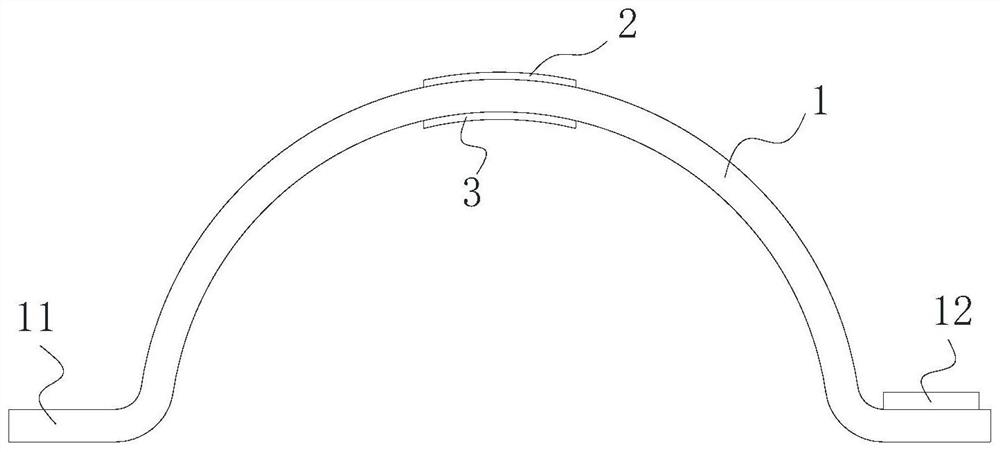
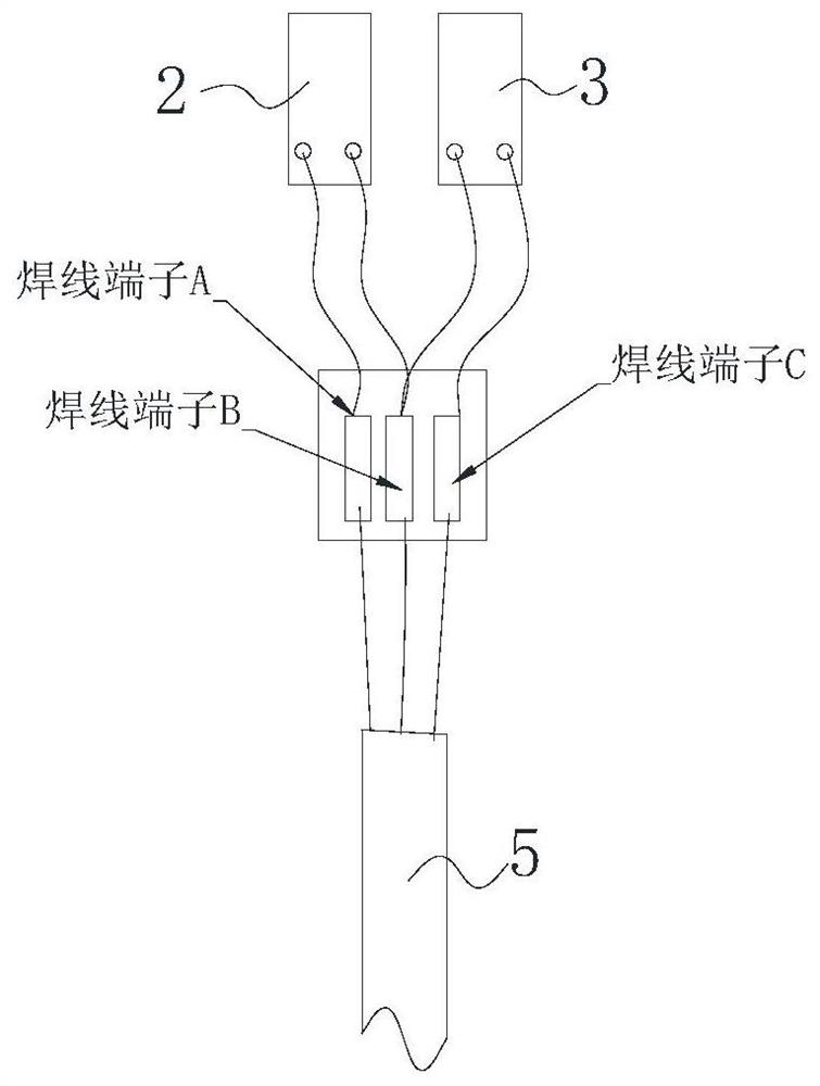
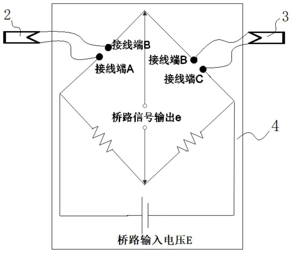
[0035] Embodiments of the present invention provide a high-precision measuring device for the dynamic displacement of structural micro-cracks, such as Figure 1 to Figure 3 As shown, it includes an arched elastic base 1 , a first strain gauge 2 and a second strain gauge 3 , and a strain measurement module 4 .

[0036] Among them, such as figure 1 As shown, the arch-shaped elastic base 1 is preferably a semicircular elastic base, which is made of elastic sheets with uniform thickness, light weight, good elasticity, and certain rigidity. The elastic sheets can be made of plastic or metal sheet. The...


PUM


Abstract

The invention discloses a high-precision measuring device and method for dynamic displacement of a structural micro-crack. An arch-shaped elastic pedestal is disposed above a predicted cracking position of the micro-crack in a spanning manner, the arc-shaped inner wall and the arc-shaped outer wall of the top of the arch-shaped elastic pedestal are correspondingly provided with a first strain gauge and a second strain gauge in an attached manner, transverse dynamic displacement changes generated by opening and closing of micro cracks on the surface of the structure are converted into bending strain changes of the upper surface and the lower surface of the top of the arched elastic base, the first strain gauge and the second strain gauge serve as half-bridge resistors respectively and are electrically connected with the strain measurement module to form a half-bridge measurement circuit. the bending strain change of the first strain gauge and the second strain gauge is measured, namely the bending strain change of the top of the arched elastic base, and the end displacement change of the arched elastic base is determined based on the linear relation between the end displacement change of the arched elastic base and the bending strain change of the arched elastic base, namely the dynamic displacement change of the micro-crack is measured.

Description

technical field [0001] The invention relates to the technical field of anti-seismic engineering structures, in particular to a high-precision measuring device and method for the dynamic displacement of structural micro-cracks. Background technique [0002] The shaking table test is one of the direct and effective methods to study the seismic characteristics of actual civil engineering structures or hydraulic engineering structures. The damage characteristics of structures under earthquakes, especially the nonlinear characteristics of structural damage, are currently research difficulties and hotspots. The dynamic change process of the vibration damage of the model structure in the simulated earthquake of the shaking table, especially the displacement evolution process of the crack after the structure cracks, can effectively reveal the structure damage mechanism. Due to the relationship between the geometric scale of the model, the cracking change of the actual structure is ...

Claims


Application Information

Patent Timeline
IPC IPC(8): G01B7/16G06F17/15
CPCG01B7/18G06F17/15
Inventor 许亮华罗国虎李春雷王海波王少华曾新翔高建勇任绍成李金伟姜明利王熙瞿洁倪马兵赵文俊李红涛王雄飞孙铭君刘扬
Owner CHINA INST OF WATER RESOURCES & HYDROPOWER RES
Why Eureka
Try Eureka