Precision machining process for hole system of main motor supporting plate of numerical control mine rope sawing machine
A technology of precision machining and main motor, applied in the direction of metal processing equipment, manufacturing tools, accessories of toolholders, etc., to achieve high precision, improve dimensional accuracy, and ensure high precision
Active Publication Date: 2022-05-13
QUANZHOU INST OF INFORMATION ENG
View PDF2 Cites 0 Cited by
- Summary
- Abstract
- Description
- Claims
- Application Information
AI Technical Summary
Problems solved by technology
[0003] In order to solve the above technical problems, the present invention provides a precision machining process for the hole system of the main motor support plate of the CNC mine wire saw machine to solve the existing problems
Method used
View moreImage
Smart ImageViewing Examples

Examples
Embodiment
[0027] as attached figure 1 to attach image 3 Shown:
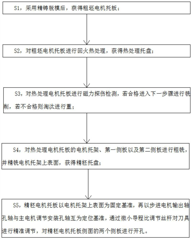
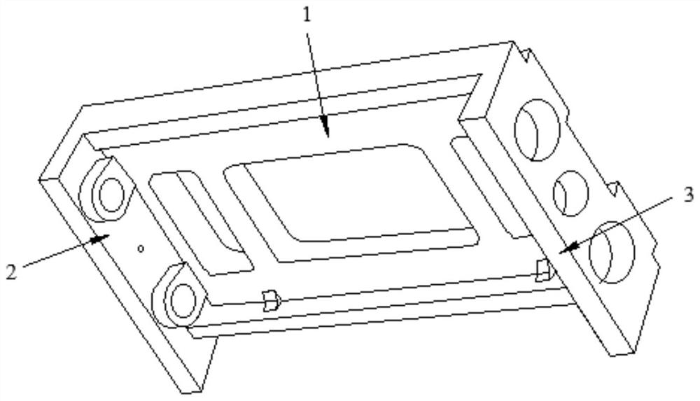
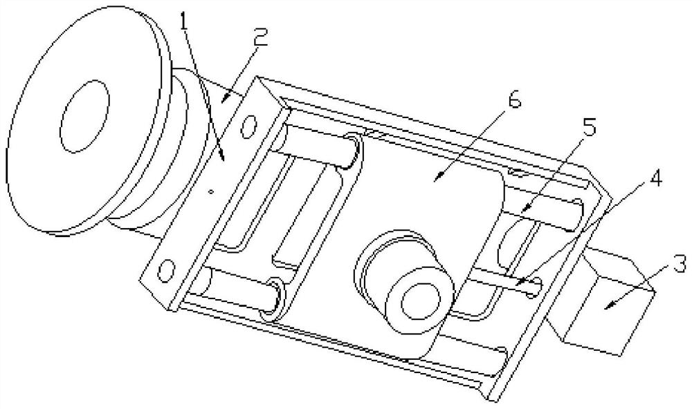
[0028] The present invention provides a precision machining process for the 1-hole system of the main motor support plate of a numerically controlled mine wire saw machine, which includes the following steps:
[0029] S1, after precision casting is used for demoulding, a rough motor pallet 1 is obtained;
[0030] S2, performing tempering heat treatment on the rough motor pallet 1 to obtain a heat treatment tray;
Login to View More PUM
| Property | Measurement | Unit |
|---|---|---|
| Length | aaaaa | aaaaa |
Abstract
The invention provides a numerical control mine wire sawing machine main motor supporting plate hole system precision machining technology which comprises the steps that S1, after precision casting demolding is adopted, a rough blank motor supporting plate is obtained; s2, the rough blank motor supporting plate is subjected to tempering heat treatment, and a heat treatment tray is obtained; s3, magnetic flaw detection is conducted on the heat treatment motor supporting plate, if the heat treatment motor supporting plate is qualified, milling is conducted in the next step, and if the heat treatment motor supporting plate is not qualified, re-machining is conducted; s4, roughly milling the motor bracket, the first side plate and the second side plate of the heat-treated motor supporting plate, and finely milling the upper surface of the motor bracket to obtain a fine blank tray; s5, taking the upper surface of the motor bracket as a fixing reference for the fine blank motor supporting plate, then taking a stepping motor output shaft hole shaft and a main motor adjusting mounting hole shaft as positioning references for each other, accurately adjusting a cutter through an adjusting screw rod with an ultra-large diameter-small lead ratio, and punching two side plates on the side surfaces of the fine blank motor supporting plate.
Description
technical field [0001] The invention belongs to the field of fine machining, and more specifically relates to a precise machining process for the hole system of the supporting plate of the main motor of a numerically controlled mine wire saw machine. Background technique [0002] The main motor support plate is the key part of the main motor of the CNC mine wire saw machine. It not only provides the main power for the wire saw machine, but also directly affects the working status of the whole machine by connecting the saw rope to the drive wheel with the support plate. The hole system for installing the screw mechanism and the guide post on the pallet requires high precision, and because the screw structure on different sides of the pallet is different from the installation hole diameter of the guide post, it is difficult to process the hole system. As a result, the completion cycle of finished products is long. Contents of the invention [0003] In order to solve the abo...
Claims
Login to View More Application Information
Patent Timeline
 IPC IPC(8): B23P15/00B23B27/00B23B29/02
CPCB23P15/00B23B27/00B23B29/02
Inventor 顾立志宋金玲高善平顾春阳肖俊彦陈核炉梁成龙
Owner QUANZHOU INST OF INFORMATION ENG