
Current sensor and current detection method

A current sensor and current technology, applied in the sensor field, can solve the problems of unmaintainable, high signal-to-noise ratio, etc., to achieve the effect of flexible use, high precision, and improved system signal-to-noise ratio

Pending Publication Date: 2022-08-05
北京普瑞姆赛斯科技有限公司
View PDF0 Cites 0 Cited by
  • Summary
  • Abstract
  • Description
  • Claims
  • Application Information

AI Technical Summary

Problems solved by technology

[0008] The purpose of the present invention is to solve the problem that the current sensor cannot maintain a high signal-to-noise ratio when the current to be measured changes in a large dynamic range, and provides a current sensor

Method used


Image

  • Current sensor and current detection method
  • Current sensor and current detection method
  • Current sensor and current detection method

Examples


Embodiment 1

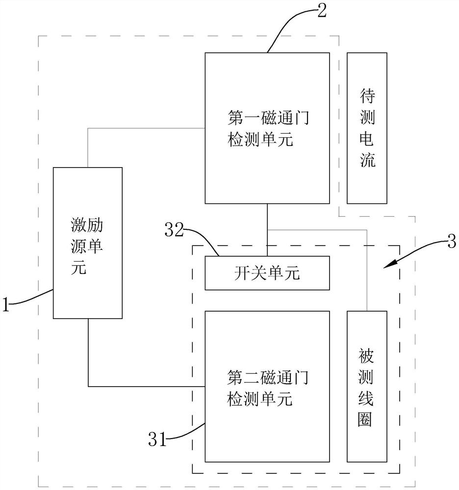
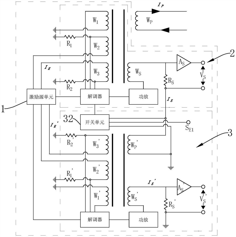
[0070] Example 1: as figure 1 As shown, this embodiment provides a current sensor, the current sensor includes an excitation source unit 1, a first fluxgate detection unit 2 and an expansion module 3, the expansion module 3 includes a second fluxgate detection unit 31, a switch unit 32 and the coil under test. The output end of the excitation source unit 1 is respectively connected to the input end of the first fluxgate detection unit 2 and the input end of the second fluxgate detection unit 31, and the output end of the first fluxgate detection unit 2 is respectively connected to the input end of the switch unit 32 and the input end of the switch unit 32. The input end of the detection coil is connected, and the first fluxgate detection unit 2 is used to detect the current to be measured, generate a first compensation current according to the current to be measured, and output the first compensation current from the current output end of the first fluxgate detection unit 2; ...

Embodiment 2

[0094] Example 2: as Figure 4 As shown, this embodiment provides a current sensor, the current sensor includes an excitation source unit 1, a first fluxgate detection unit 2 and an expansion module 3, and the expansion module 3 includes a first expansion module 3 and a second expansion module 3 , the first expansion module 3 and the second expansion module 3 have the same structure and connection relationship, but the size, size and specification of each element are different; the output end of the excitation source unit 1 is respectively connected with the input end of the first fluxgate detection unit 2, the The input end of the expansion module 3 is connected to the input end of the second expansion module 3, and the output end of the first fluxgate detection unit 2 is respectively connected with the input end of the switch unit 32 in the first expansion module 3 and the coil under test in the first expansion module 3 The input end is connected, and the output end of the s...


PUM

PropertyMeasurementUnit
Snraaaaaaaaaa

Abstract

The invention discloses a current sensor and a current detection method, the current sensor comprises an excitation source unit, a first fluxgate detection unit and an expansion module, the expansion module comprises a second fluxgate detection unit, a switch unit and a detected coil; the excitation source unit is respectively connected with the first fluxgate detection unit and the second fluxgate detection unit; the current output end of the first fluxgate detection unit is connected with the input end of the switch unit; the input end of the tested coil is connected with the input end of the switch unit; the conduction state of the switch unit is determined based on the target precision and the target range of the current sensor; the current detection method is based on the current sensor, and the to-be-detected current is calculated through the compensation current. According to the invention, the problem that the current sensor cannot maintain a high signal-to-noise ratio when the to-be-measured current changes in a large dynamic range is solved, and the high precision of current measurement is ensured.

Description

technical field [0001] The invention relates to the field of sensors, in particular to a current sensor and a current detection method. Background technique [0002] The current current sensor is a proportional conversion device with a single range. Since its secondary coil has been solidified inside the sensor, its range is single. Due to the existence of the signal-to-noise ratio, the measurement accuracy is affected. In particular, according to the requirements of different application scenarios, the signal-to-noise ratio requirements of current sensors are not consistent, especially in the field of high-energy physics, the dynamic range of the measured signal is large, and a single-range current sensor usually cannot guarantee a higher signal under a large dynamic range. Noise ratio, i.e. accuracy over a large dynamic range cannot be guaranteed. [0003] In the prior art, the excitation source uses a periodic signal of a certain frequency to excite the magnetic core to ...

Claims


Application Information

Patent Timeline
IPC IPC(8): G01R15/20G01R19/00
CPCG01R15/20G01R19/0092
Inventor 李斌孙向平韩冰李越超石梦瑶冯硕龙高金伟
Owner 北京普瑞姆赛斯科技有限公司
Learn More