
Porous silicon heating structure with oil storage packaging structure and electronic cigarette comprising porous silicon heating structure

A packaging structure, porous silicon technology, applied in the field of electronic cigarettes, can solve the problems of poor heating uniformity, short service life of ceramic atomization and cotton wick atomization, affecting the taste of smoking, etc., and achieves long service life, uniform and reliable heating and atomization. , good atomization effect

Pending Publication Date: 2022-01-11
SHENZHEN KELAI PENG TECH CO LTD
View PDF0 Cites 0 Cited by
  • Summary
  • Abstract
  • Description
  • Claims
  • Application Information

AI Technical Summary

Problems solved by technology

[0003] The traditional electronic cigarette structure generally includes a host and a pod. The host is used for power supply and control to connect the pod. The pod is equipped with an e-liquid and an atomization structure. The host controls the atomization structure to heat the e-liquid to achieve atomization of the e-liquid. Electronic cigarettes need to use heating components to heat the e-liquid when heating and atomizing the e-liquid. The existing atomization structure generally adopts ceramic atomization or cotton core atomization, and ceramic atomization and cotton core atomization are used Short life, poor heating uniformity, affecting the taste of smoking

Method used


Image

  • Porous silicon heating structure with oil storage packaging structure and electronic cigarette comprising porous silicon heating structure
  • Porous silicon heating structure with oil storage packaging structure and electronic cigarette comprising porous silicon heating structure

Examples


Embodiment Construction

[0020] In order to facilitate the understanding of the present invention, the present invention will be described more fully below with reference to the associated drawings. Preferred embodiments of the invention are shown in the accompanying drawings. However, the present invention can be embodied in many different forms and is not limited to the embodiments described herein. Rather, these embodiments are provided so that the understanding of the disclosure of the present invention will be thorough.

[0021] It should be noted that when an element is referred to as being "fixed to" another element, it can be directly on the other element or an intervening element can also be present. When an element is said to be "connected" to another element, it can be directly connected to the other element or intervening elements may also be present.

[0022] Unless otherwise defined, all technical and scientific terms used herein have the same meaning as commonly understood by one of o...


PUM

PropertyMeasurementUnit
Thickness dimensionaaaaaaaaaa
Aperture sizeaaaaaaaaaa
Apertureaaaaaaaaaa

Abstract

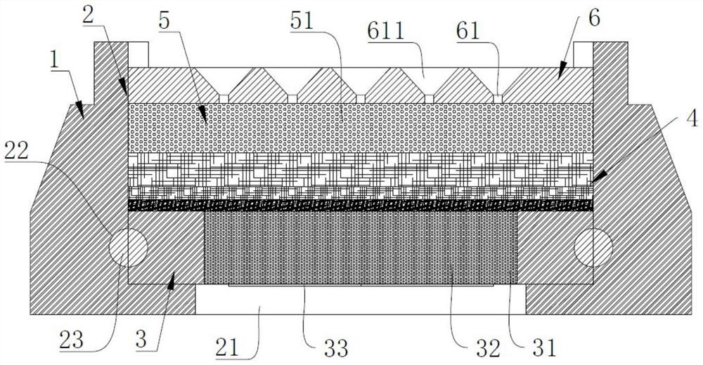
The invention relates to the technical field of electronic cigarettes, in particular to a porous silicon heating structure with an oil storage packaging structure and an electronic cigarette comprising the porous silicon heating structure, and the porous silicon heating structure comprises a fixed seat, an atomization cavity formed in the fixed seat, and a heating sheet body, oil storage cotton, an oil conveying sheet and an oil guide sheet which are sequentially arranged in the atomization cavity from bottom to top, and the heating sheet body is provided with a permeation area; micropores are uniformly distributed in the permeation area, the micropores are connected with the oil storage cotton, oil conveying holes are uniformly distributed in the oil conveying sheet, the oil conveying holes are communicated with the oil storage cotton, a heating circuit is arranged on the heating sheet body, oil guide holes are formed in the oil guide sheet, and the oil guide holes are communicated with the oil conveying holes; the heating circuit is arranged in the permeation area and deviates from one surface of the oil storage cotton; through the cooperation of the oil conveying sheet and the oil storage cotton, the electronic cigarette can be used for storing tobacco tar, sufficient tobacco tar can be conveniently provided when the electronic cigarette is used every time, the heating and atomizing effects on the tobacco tar are good, and the taste is improved.

Description

technical field [0001] The invention relates to the technical field of electronic cigarettes, in particular to a porous silicon heating structure with an oil storage packaging structure and an electronic cigarette containing the same. Background technique [0002] Electronic cigarettes are mainly used to quit and replace cigarettes. It can simulate the taste of cigarettes, but when smoking electronic cigarettes, it will not release tar, nicotine and second-hand smoke that are harmful to the human body. It can improve the success rate of smoking cessation with nicotine replacement therapy. [0003] The traditional electronic cigarette structure generally includes a host and a pod. The host is used for power supply and control to connect the pod. The pod is equipped with an e-liquid and an atomization structure. The host controls the atomization structure to heat the e-liquid to achieve atomization of the e-liquid. Electronic cigarettes need to use heating components to heat t...

Claims


Application Information

Patent Timeline
IPC IPC(8): A24F40/10A24F40/48A24F40/40
CPCA24F40/10A24F40/48A24F40/40
Inventor 李博
Owner SHENZHEN KELAI PENG TECH CO LTD
Learn More