High-stability machining clamp

A machining and high stability technology, applied in the direction of manufacturing tools, metal processing equipment, metal processing machinery parts, etc., to achieve the effects of high stability, efficient driving, and improved processing accuracy

Active Publication Date: 2022-01-11
SHENZHEN JINGDIAO CNC EQUIP
View PDF3 Cites 1 Cited by
  • Summary
  • Abstract
  • Description
  • Claims
  • Application Information

AI Technical Summary

Problems solved by technology

[0004] The present invention provides a highly stable machining fixture to solve the problem that in the prior art, the side plates on both sides of the slot of the work

Method used


Image

  • High-stability machining clamp
  • High-stability machining clamp
  • High-stability machining clamp

Examples


Embodiment Construction

[0039] The following will clearly and completely describe the technical solutions in the embodiments of the present invention with reference to the accompanying drawings in the embodiments of the present invention. Obviously, the described embodiments are only some, not all, embodiments of the present invention. Based on the embodiments of the present invention, all other embodiments obtained by those skilled in the art without making creative efforts belong to the protection scope of the present invention.

[0040] Directional terms mentioned in the present invention, such as "up", "down", "front", "back", "left", "right", "inside", "outside", "side", "top" Words such as "bottom" and "bottom" only refer to the orientation of the drawings, and the directional terms used are used to illustrate and understand the present invention, but not to limit the present invention.

[0041] Words such as "first" and "second" in the terminology of the present invention are only used for des...


PUM


Abstract

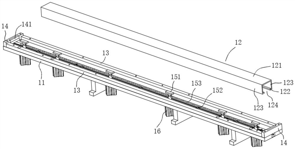
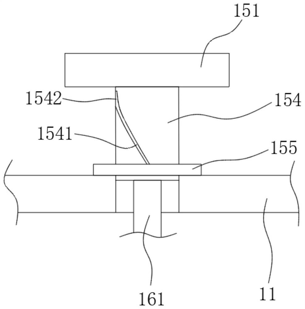
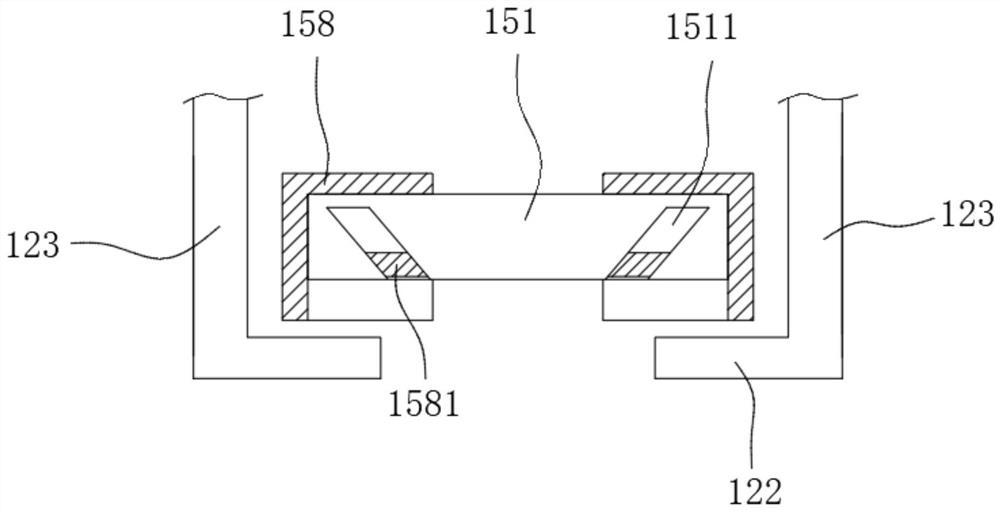
The invention provides a high-stability machining clamp. The high-stability machining clamp comprises a bottom plate, transverse positioning blocks, longitudinal positioning blocks, a clamping and fixing assembly and a driving part. The transverse positioning blocks and the longitudinal positioning blocks are fixed to the bottom plate, the transverse positioning blocks and the longitudinal positioning blocks are arranged on the outer sides of the two third wall plates, and the clamping and fixing assembly is connected with the bottom plate, located between the transverse positioning blocks, penetrates into the open groove and extends to the inner side of a workpiece. The clamping and fixing assembly comprises a vertical clamping and fixing assembly for clamping and fixing a second wall plate and a transverse clamping and fixing assembly for extruding and supporting the third wall plate; and the driving part is arranged on the side, away from the clamping and fixing assembly, of the bottom plate, penetrates through the bottom plate to be connected with the clamping and fixing assembly and is used for driving the clamping and fixing assembly to clamp or loosen the workpiece. According to the high-stability machining clamp, the driving part is used for controlling the clamping and fixing assembly to support a workpiece in the vertical direction and the transverse direction from the inner side, so that the stability is high during machining, driving is efficient, and the machining precision can be improved.

Description

technical field [0001] The invention relates to the field of machining fixtures, in particular to a highly stable machining fixture. Background technique [0002] The machining fixture is a device on the machine tool to clamp the workpiece and guide the tool. Refers to a fixture specially designed for a certain process of a certain workpiece. It is characterized by compact structure, fast, convenient and labor-saving operation, and can guarantee high processing accuracy and production efficiency, but the design and manufacturing cycle is long and the manufacturing cost is also high. It is mainly suitable for the production of fixed products and large batches. It is used to determine the correct position of the workpiece in the fixture, so as to ensure the relative correct position of the workpiece relative to the tool and the machining movement of the machine tool during processing. For a workpiece with slots on one side, the fixtures in the prior art cannot efficiently an...

Claims


Application Information

Patent Timeline
IPC IPC(8): B23Q3/08
CPCB23Q3/08
Inventor 周志修
Owner SHENZHEN JINGDIAO CNC EQUIP
Why Eureka
Try Eureka