Dynamic synchronous loading test device and method for deformed wing

A loading test device and wing technology, which is used in the testing of aircraft components, and the use of stable tension/pressure to test the strength of materials, etc. Synchronized effect

Pending Publication Date: 2022-01-11
SHANGHAI JIAO TONG UNIV
View PDF0 Cites 0 Cited by
  • Summary
  • Abstract
  • Description
  • Claims
  • Application Information

AI Technical Summary

Problems solved by technology

The deformed wing will deform according to different flight states in the air, so that the aircraft can achieve the best flight performance. The current loading test device can only load a certain fixed shape of the wing, and cannot load it during the entire deformation process.
[0003] The existing loading technology is only applicable to the fixed wing, that is, the wing does not undergo relative deformation in the horizontal plane and the existing loading method is stationary relative to the mounting plate, and cannot realize its own movement, so it cannot meet the requirements of the wing. Synchronous deformation of

Method used


Image

  • Dynamic synchronous loading test device and method for deformed wing
  • Dynamic synchronous loading test device and method for deformed wing
  • Dynamic synchronous loading test device and method for deformed wing

Examples


Embodiment Construction

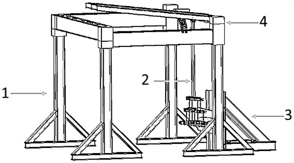
[0018] Such as figure 2 As shown, it is a dynamic synchronous loading test device for a deformed wing involved in this embodiment, including: a loading frame 1, a lever system 2, a loading base 3 and a loading motion system 4, wherein: the loading motion system 4 passes through the loading frame 1 Set on the loading base 3, the wing test piece 5 is suspended by the lever system 2 and loaded by the motion system 4.

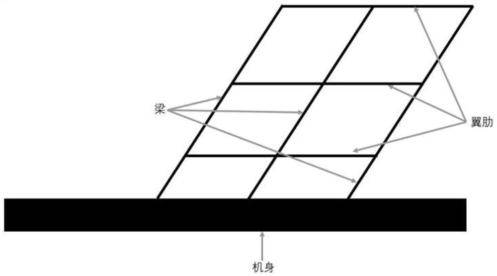
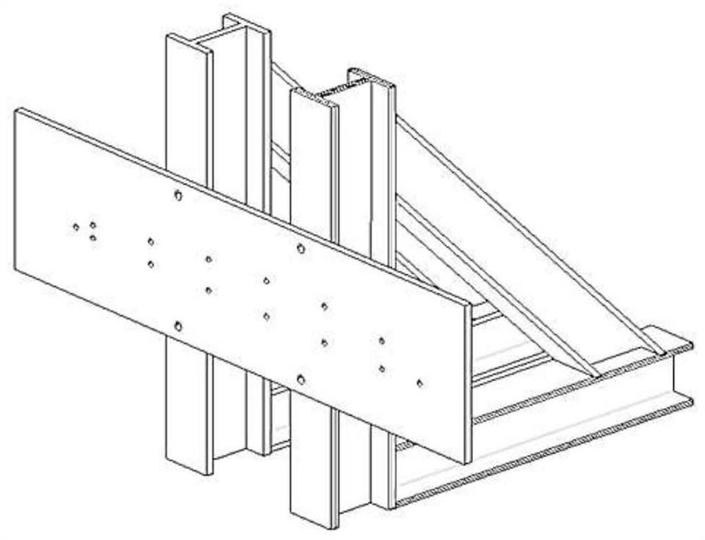
[0019] Such as image 3 As shown, the loading base 3 is fixed on the ground by bolts, and the wing test piece is installed through the mounting holes on the mounting plate, and a parallelogram is formed between the beam and the rib of the swept wing of the wing test piece.

[0020] Such as Figure 4 As shown, the lever system 2 specifically includes: several groups of lever branches 201, and each lever branch 201 is further connected to the surface of the wing test piece 5 through at least one layer of lever branches.

[0021] For the lever branch, after select...


PUM


Abstract

The invention relates to a dynamic synchronous loading test device and method for a deformed wing, the dynamic synchronous loading test device comprises a loading frame, a lever system, a loading base and a loading motion system, the loading motion system is arranged on the loading frame and is located on the loading base, and a wing test piece is arranged on the loading base and is connected with the lever system and is located below the loading motion system. Compared with the prior art, the dynamic synchronous loading characteristic is better.

Description

technical field [0001] The invention relates to a technology in the field of aircraft manufacturing, in particular to a dynamic synchronous loading test device and method for deformed wings Background technique [0002] variable-sweep wings figure 1 As shown, the swept wing structure is composed of beams and ribs, and the beams and ribs form a parallelogram structure, such as figure 1 As shown, the sweep angle can be changed by changing the angle between the wing and the fuselage. The wing generally simulates the complex loads that the wing is subjected to in the air to test the strength, stiffness, stress and deformation distribution of the wing under load to obtain an effective estimate, which provides an important reference for subsequent work. The deformed wing will deform according to different flight states in the air, so that the aircraft can achieve the best flight performance. The current loading test device can only load a certain fixed shape of the wing, and can...

Claims


Application Information

Patent Timeline
Patent Type & Authority Applications(China)
IPC IPC(8): B64F5/60G01N3/08
CPCB64F5/60G01N3/08
Inventor 马天瑞周翔
Owner SHANGHAI JIAO TONG UNIV
Why Eureka
Try Eureka