New energy automobile cooling joint drawing detection mechanism

A technology for new energy vehicles and testing institutions, which is applied to measurement devices, testing of mechanical parts, optical testing flaws/defects, etc., can solve the problems of obvious detection and unsatisfactory detection effect, and achieve the effect of improving the detection effect.

Pending Publication Date: 2022-01-11
CHONGQING SULIAN AUTO PARTS
View PDF6 Cites 0 Cited by
  • Summary
  • Abstract
  • Description
  • Claims
  • Application Information

AI Technical Summary

Problems solved by technology

[0003] The power battery, drive motor and electronic control system in new energy vehicles are used as heating devices, which will generate losses during the movement, and these losses will be dissipated in the form of heat. Therefore, water-cooled or air-cooled heat sinks are often used to bring To dissipate the heat generated by the drive motor, no matter the water-cooled or air-cooled heat sink is connected to multiple cooling pipes through the cooling joint; the cooling joint is usually welded on the cooling pipe, in order to determine whether the cooling joint is welded to the pipe It is solid and reliable. Generally, the cooling joint is pulled out and tested by a puller, and then the firmness of the welding is determined by the naked eye of the staff. This kind of testing method can only detect obvious welding problems, slightly small spot welds, single It is difficult to observe with the naked eye, which leads to a very unsatisfactory detection effect

Method used


Image

  • New energy automobile cooling joint drawing detection mechanism
  • New energy automobile cooling joint drawing detection mechanism
  • New energy automobile cooling joint drawing detection mechanism

Examples


Embodiment Construction

[0023] The following will clearly and completely describe the technical solutions in the embodiments of the present invention with reference to the accompanying drawings in the embodiments of the present invention. Obviously, the described embodiments are only some, not all, embodiments of the present invention. Based on the embodiments of the present invention, all other embodiments obtained by persons of ordinary skill in the art without making creative efforts belong to the protection scope of the present invention.

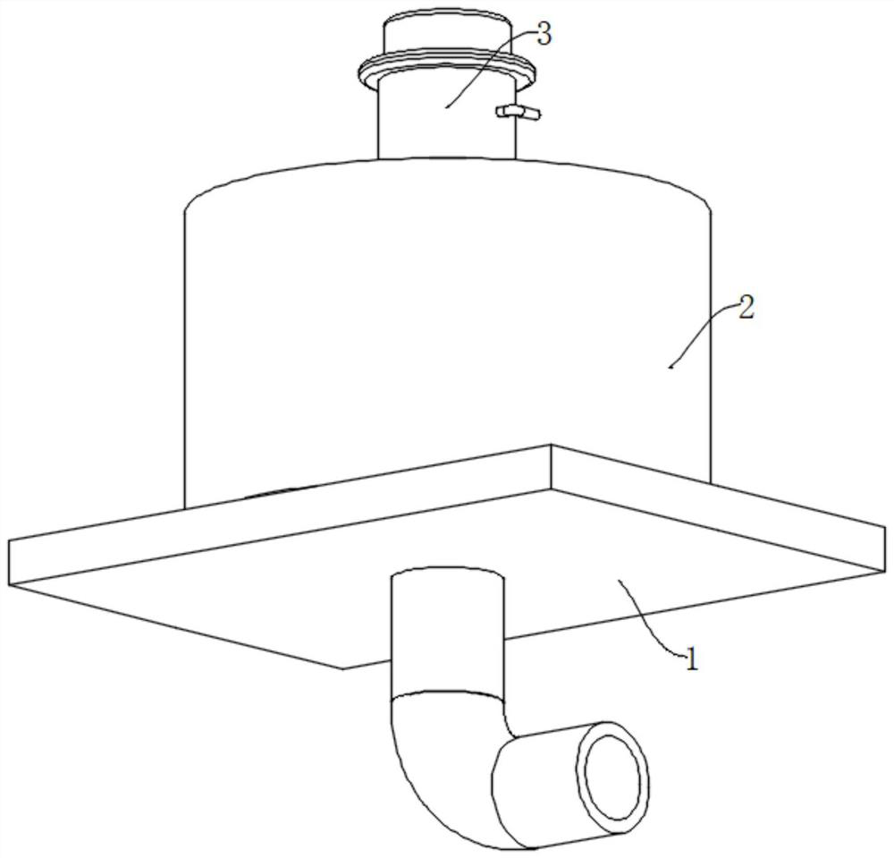
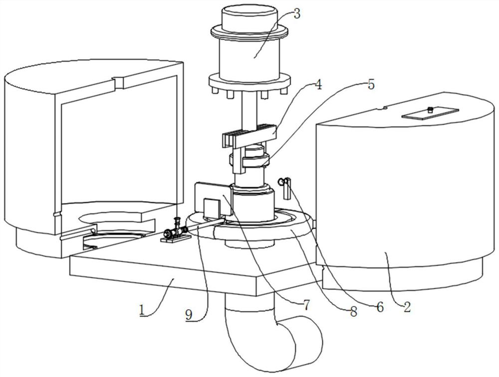
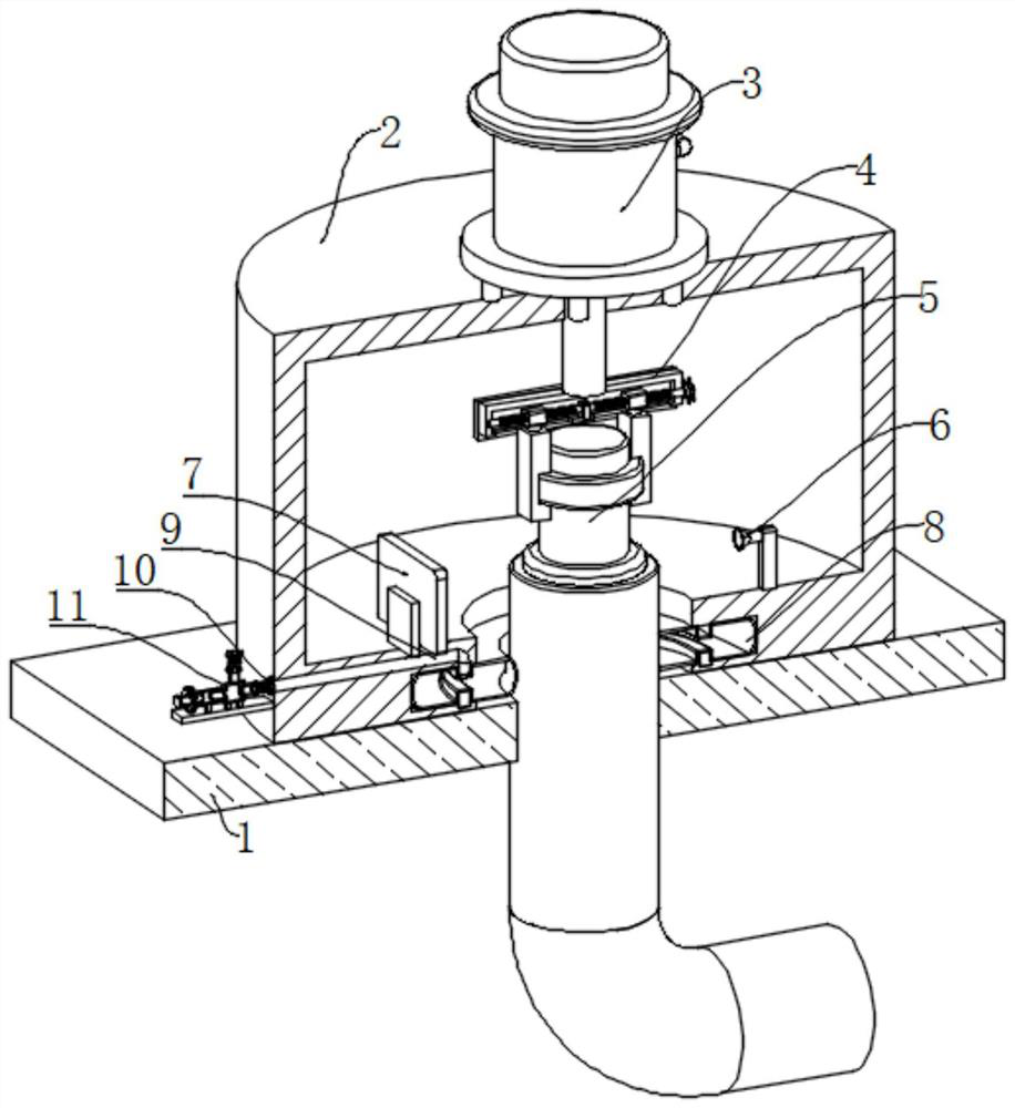
[0024] see Figure 1 to Figure 5 , the present invention provides a technical solution: the new energy vehicle cooling joint drawing detection mechanism, including the cooling joint 5 and the drawing detection mechanism arranged on the vehicle plate 1, the cooling joint 5 is welded on the pipeline on the vehicle plate 1, and the pulling The pull detection mechanism includes a light shield 2, a puller 3, a clamping mechanism 4, a searchlight 6, and a photosensi...


PUM


Abstract

The invention relates to the technical field of new energy vehicles, in particular to a new energy automobile cooling joint drawing detection mechanism which comprises a cooling joint arranged on a vehicle plate and a drawing detection mechanism, and the drawing detection mechanism comprises a light blocking cover, a drawing instrument, a clamping mechanism, a searchlight and a light sensing plate. The light blocking cover is arranged on the outer side of the cooling joint in a sleeving mode and horizontally placed on the vehicle plate, the drawing instrument is fixedly arranged on the light blocking cover, a pull rod of the drawing instrument extends into the light blocking cover and is fixedly connected with the clamping mechanism, the clamping mechanism clamps or loosens the cooling joint, a circular through hole is formed in the middle of the lower end of the light blocking cover, and an annular groove is formed in the side wall of the circular through hole; an air bag is arranged in the annular groove and controlled by an inflation and deflation assembly to be inflated or deflated. The light blocking cover is arranged to be matched with the searchlight and the light sensing plate for use, and whether the new energy joint is firmly and reliably welded or not can be accurately and effectively recognized.

Description

technical field [0001] The invention relates to the technical field of new energy vehicles, in particular to a pulling detection mechanism for cooling joints of new energy vehicles. Background technique [0002] As energy and environmental issues become the focus of attention on a global scale, electric vehicles with drive motors and power batteries instead of traditional internal combustion engines, and power batteries as power sources, will become one of the important development directions of the automotive industry in the future due to their advantages in environmental protection and energy saving. one. New energy vehicles refer to vehicles that use unconventional vehicle fuels as power sources, integrate advanced technologies in vehicle power control and drive, and form vehicles with advanced technical principles, new technologies, and new structures. [0003] The power battery, drive motor and electronic control system in new energy vehicles are used as heating device...

Claims


Application Information

Patent Timeline
Patent Type & Authority Applications(China)
IPC IPC(8): G01M13/00G01M3/38G01N21/88
CPCG01M13/00G01M3/38G01N21/88
Inventor 吕娟曹树林李旭阳徐明朱世鹏徐梓净杨毅韩宗俊
Owner CHONGQING SULIAN AUTO PARTS
Why Eureka
Try Eureka