Motor capable of prolonging service life of oil-retaining bearing

A bearing life and bearing technology, which is applied in the direction of electrical components, electromechanical devices, mechanical equipment, etc., can solve the problems of stuck friction loss, failure to reach oil storage, and failure to form oil storage chambers, etc., to increase the life of oil-containing bearings and reduce The effect of loss

Pending Publication Date: 2022-01-11
SHANGHAI MOONS ELECTRICAL APPLIANCE
View PDF2 Cites 0 Cited by
  • Summary
  • Abstract
  • Description
  • Claims
  • Application Information

AI Technical Summary

Problems solved by technology

This design cannot achieve the purpose of oil storage, even if the design mentions adding an anti-leakage ring at both ends of the oil-impregnated bearing
The reasons are as follows: 1) The inner diameter of the oil-impregnated bearing is loosely matched with the shaft, and a sealed oil storage chamber cannot be formed; 2) The leak-proof ring is closely attached to the oil-impregnated bearing. If the axial seal is to be achieved, the leak-proof ring must be closely attached to the rotating shaft , so that the motor itself will cause jamming or a large friction loss

Method used


Image

  • Motor capable of prolonging service life of oil-retaining bearing
  • Motor capable of prolonging service life of oil-retaining bearing
  • Motor capable of prolonging service life of oil-retaining bearing

Examples


Embodiment 1

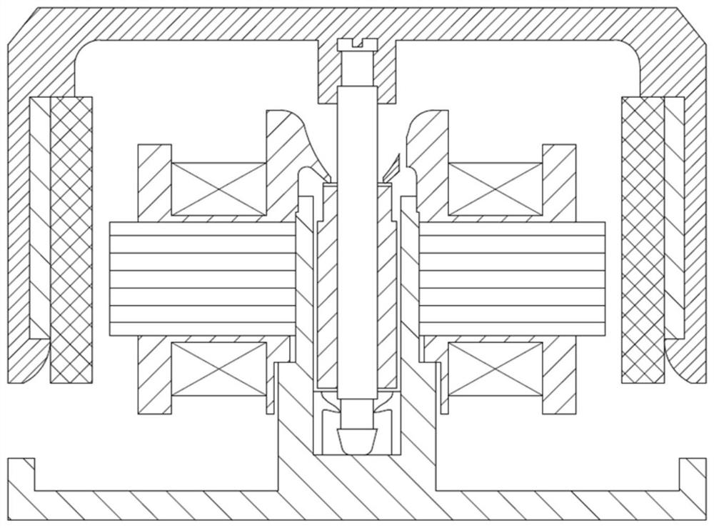
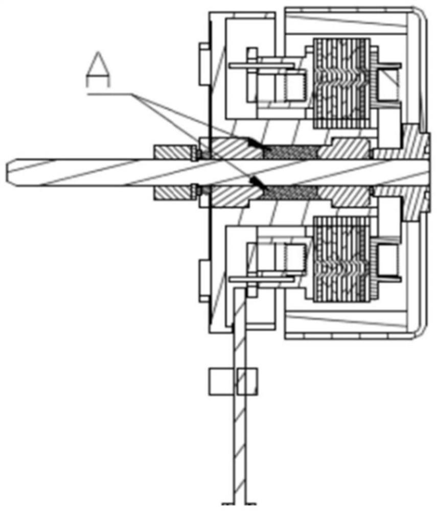
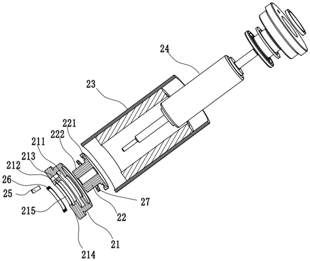
[0033] Such as Figure 3-4 As shown, a motor that can prolong the service life of the oil-impregnated bearing includes an end cover 21, an oil-impregnated bearing 22, a stator 23 and a rotor 24, and the rotor 24 is mounted on the oil-impregnated bearing 22 after being loaded into the stator 23, and the described The oil-impregnated bearing 22 is installed in the end cover 21, and the end cover 21 is provided with a bearing chamber 215 and an oil filling port 212. The bearing chamber 215 is provided with an oil storage tank 211, and the oil storage tank 211 is a circular ring with a rectangular cross section or other arbitrary cross section. Shaped rotary structure. One end of the oil storage tank 211 is inside the end cover 21, and the other end is in contact with the outer surface of the oil bearing 22. The oil filling port 212 is opened in the axial direction, one end is connected to the oil storage tank 211, and the other end is connected to the outer end surface 214 of the...

Embodiment 2

[0038] Such as Figure 5 and 6 As shown, the oil storage tank 211 is a first circular ring 211' with a required angle. Preferably, the angle of the first circular ring 211' is 180°. This design can leave the required space in the end cover, so that the motor that needs to go out has space to process the wire hole.

Embodiment 3

[0040] Such as Figure 7 and 8 As shown, the oil storage tank 211 is a plurality of second rings 211 ″ with a set angle, and the number of the oil filling ports 212 is the same as the number of the second rings 211 ″. Preferably, the multiple second rings 211" have the same angle and are evenly distributed. This design facilitates the addition of customer installation holes on the front cover. Correspondingly, the number of oil injection holes and rubber plugs must be consistent with the number of oil storage tanks.


PUM


Abstract

The invention relates to a motor capable of prolonging the service life of an oil-retaining bearing. The motor comprises an end cover, the oil-retaining bearing, a stator and a rotor, the rotor is mounted on the oil-retaining bearing together with the stator after being mounted in the stator, the oil-retaining bearing is mounted in the end cover, the end cover is provided with a bearing chamber and an oil filling port, an oil storage tank is arranged in the bearing chamber, one end of the oil storage tank is arranged in the end cover, the other end of the oil storage tank is in contact with the outer circular surface of the oil bearing, and the oil injection port is axially formed with one end connected with the oil storage tank and the other end connected with the outer end surface of the end cover. Compared with the prior art, the motor can be installed in any mode, and the service life of the oil-retaining bearing is greatly prolonged.

Description

technical field [0001] The invention relates to a motor, in particular to a motor capable of prolonging the service life of an oil-impregnated bearing. Background technique [0002] Oil-impregnated bearings have been widely used because of their low cost, convenient use, easy control of size, and various shapes. However, with the advancement of technology, higher requirements are put forward for the use environment of oil-impregnated bearings, especially in the environment where low temperature and high temperature coexist, which intensifies the loss of oil-impregnated bearing oil and reduces the service life. How to ensure sufficient oil bearing grease has become a key technology to prolong the life of oil bearings. [0003] For example, if figure 1 As shown, Chinese Patent Publication No. CN103248161B discloses a motor with oil storage function, which discloses an enlarged oil storage space connected to the oil return passage between the stop part of the insulating sleev...

Claims


Application Information

Patent Timeline
Patent Type & Authority Applications(China)
IPC IPC(8): H02K5/16H02K5/124H02K5/04F16N1/00
CPCH02K5/161H02K5/124H02K5/04F16N1/00
Inventor 李志辉陈源金万兵
Owner SHANGHAI MOONS ELECTRICAL APPLIANCE
Why Eureka
Try Eureka