Pilot-operated type hydraulic electromagnetic valve for airplane braking

A hydraulic solenoid valve and pilot-operated technology, which is applied in the field of hydraulic solenoid valves, can solve the problems of not being able to meet the long-term working requirements of the hydraulic braking system of aviation aircraft, failing to meet the requirements of the hydraulic braking system of aviation aircraft, and not applicable to functions and performance. Achieve the effect of light weight, strong anti-pollution ability and small size

Active Publication Date: 2020-08-07
XIAN AVIATION BRAKE TECH
View PDF7 Cites 0 Cited by
  • Summary
  • Abstract
  • Description
  • Claims
  • Application Information

AI Technical Summary

Problems solved by technology

In addition, the pollution control of aircraft hydraulic brake system refers to the control of oil and hydraulic components, and the pollution resistance of hydraulic components determines the life of the system to a large extent; It is suitable for the function and performance requirements of the aircraft hydraulic brake system, and cannot meet the long-term work requirements of the aircraft hydraulic brake system, and cannot meet the technical parameter requirements of the aircraft hydraulic brake system.
After searching domestic and foreign aircraft hydraulic brake system pilot hydraulic solenoid valve products, there is no relevant pilot hydraulic solenoid valve report

Method used


Image

  • Pilot-operated type hydraulic electromagnetic valve for airplane braking
  • Pilot-operated type hydraulic electromagnetic valve for airplane braking
  • Pilot-operated type hydraulic electromagnetic valve for airplane braking

Examples


Embodiment Construction

[0039] In order to make the purpose, technical solution and advantages of the present invention more clear, the embodiments of the present invention will be described in detail below in conjunction with the accompanying drawings. It should be noted that, in the case of no conflict, the embodiments in the present application and the features in the embodiments can be combined arbitrarily with each other.

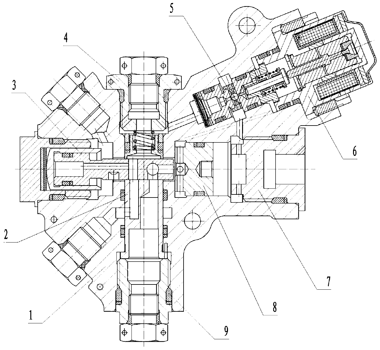
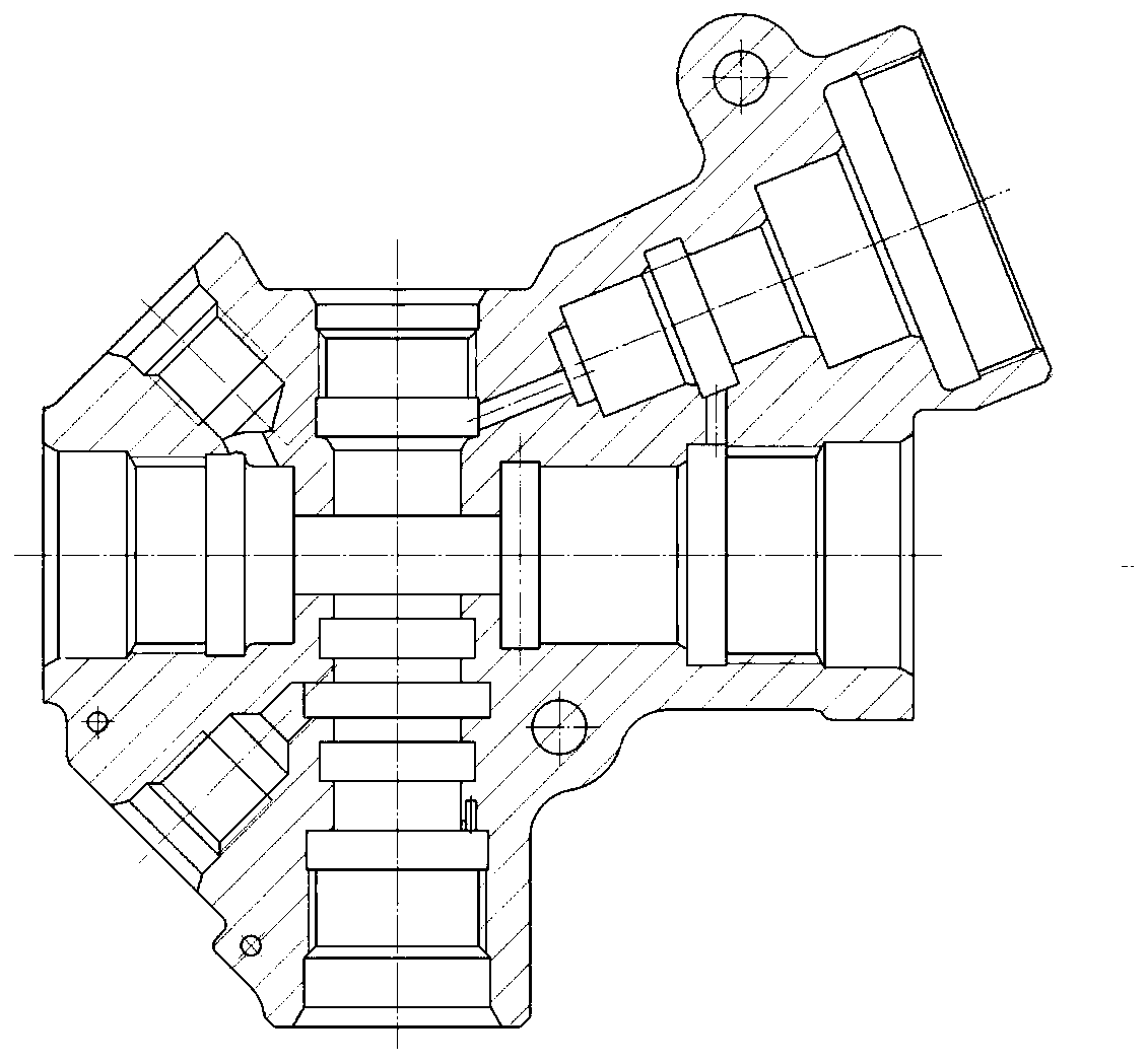
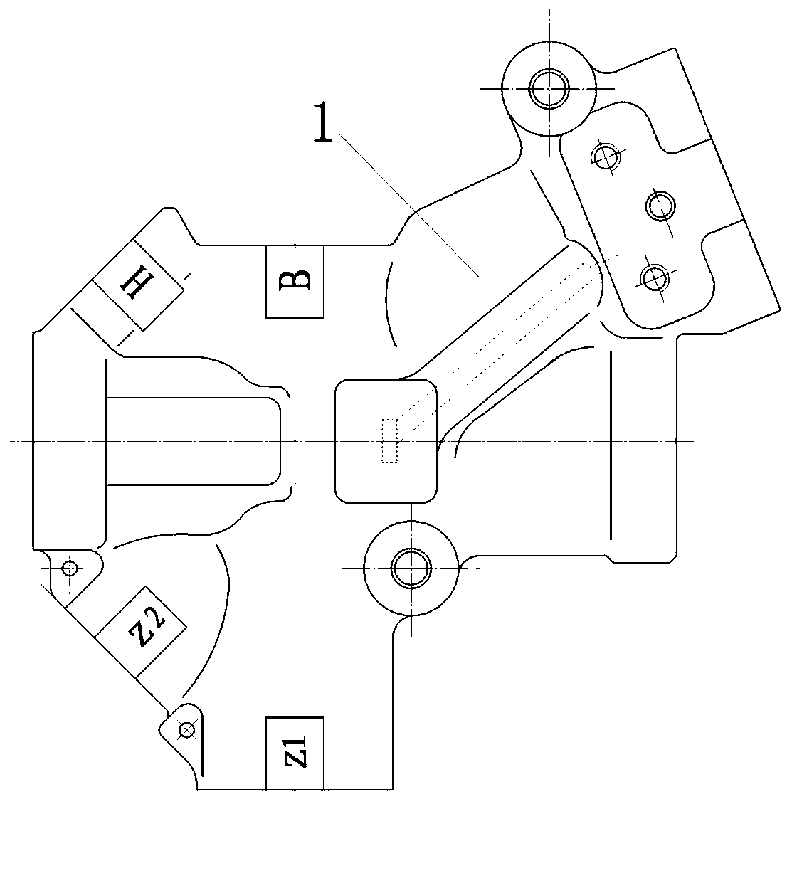
[0040] It has been explained in the background art above that the hydraulic solenoid valve is an important hydraulic control element in the aircraft braking system. It is suitable for hydraulic solenoid valves in aircraft hydraulic braking systems, and should generally have the following technical characteristics:

[0041] a), small size and light weight;

[0042] b), low power consumption; fast response, low noise;

[0043] c), strong anti-pollution ability;

[0044] d), Long-term type, high working reliability.

[0045] The influence of noise and anti-pollution ability ...


PUM


Abstract

The embodiment of the invention discloses a pilot-operated type hydraulic electromagnetic valve for airplane braking. The pilot-operated type hydraulic electromagnetic valve comprises a shell, a base,a sliding valve, a converter, an electromagnet assembly, a screw plug and a piston. An upper cavity, a lower cavity, a left cavity, a right cavity, an inclined cavity, an oil return cavity and an oiloutlet cavity which are communicated with one another are formed in the shell; the slide valve is mounted in the left cavity of the shell, and one end of the slide valve penetrates through the cross-linking area in the cavity to penetrate into the right cavity; the base is mounted in the lower cavity of the shell; the piston is arranged in the right cavity of the shell; the converter and the electromagnet assembly are sequentially installed in the inclined cavity of the shell, and the electromagnet assembly tightly presses the converter in the shell. A steel ball is arranged in the converter,the position of the steel ball is controlled through the electromagnet assembly so as to connect or disconnect an oil way of the upper cavity and an oil way of the right cavity of the shell, and thesliding valve is made to be located at different positions through sliding so as to communicate different oil ways. The electromagnetic valve provided by the embodiment of the invention can meet the requirements of an aircraft hydraulic brake system, and the working reliability of the aircraft hydraulic brake system is improved.

Description

technical field [0001] This application relates to but not limited to the technical field of hydraulic solenoid valves, in particular to an aircraft brake pilot hydraulic solenoid valve. Background technique [0002] The aircraft brake system bears the static weight and dynamic impact load of the aircraft and absorbs the kinetic energy of the aircraft when it lands, so as to realize the braking and control of the aircraft's take-off, landing, and turning. The aircraft braking system is divided into: normal braking system (also known as: main braking system), emergency braking system (also known as: backup main braking system), take-off and parking braking system, parking braking system and landing gear retraction braking system. Stop the system. In order to realize the various functions of aircraft hydraulic brakes, the aircraft hydraulic brake system needs to carry out remote automatic control of the oil flow, and the switching of various functions of the aircraft hydrauli...

Claims


Application Information

Patent Timeline
Patent Type & Authority Applications(China)
IPC IPC(8): B60T13/68B64C25/42
CPCB60T13/68B60T13/686B64C25/42
Inventor 王衡王蕾张平
Owner XIAN AVIATION BRAKE TECH
Why Eureka
Try Eureka