Vehicle-mounted visual acquisition device and unmanned vehicle

A visual acquisition and vehicle-mounted technology, applied in measuring devices, TVs, color TVs, etc., can solve problems such as failure to start, affect the camera line of sight, affect driving performance and safety, and achieve the effect of ensuring normal operation

Pending Publication Date: 2022-01-11
BEIJING SANKUAI ONLINE TECH CO LTD
View PDF0 Cites 2 Cited by
  • Summary
  • Abstract
  • Description
  • Claims
  • Application Information

AI Technical Summary

Problems solved by technology

Taking the camera as an example, during the driving process, dirt in the natural environment, such as rain, snow, dust, leaves, shellac, etc., will adhere to the lens of the camera, affecting the camera's acquisition of the surrounding environment, thereby affecting the driving performance and security
In related technologies, the commonly used solution is to spray glass water on the lens and then blow it off with air. This method is suitable for cleaning the floating dust or water-soluble stains on the surface. When encountering shellac, heavy rain, heavy snow, etc. Difficult to clean; the surface of the lens can also be wiped clean by using the wiper movement and spraying glass water, and the cleaning effect can be achieved by controlling the frequency of the wiper movement according to different situations, but because the moving wiper will affect the camera line of sight, it cannot start up

Method used


Image

  • Vehicle-mounted visual acquisition device and unmanned vehicle
  • Vehicle-mounted visual acquisition device and unmanned vehicle
  • Vehicle-mounted visual acquisition device and unmanned vehicle

Examples


Embodiment Construction

[0031] Specific embodiments of the present disclosure will be described in detail below in conjunction with the accompanying drawings. It should be understood that the specific embodiments described here are only used to illustrate and explain the present disclosure, and are not intended to limit the present disclosure.

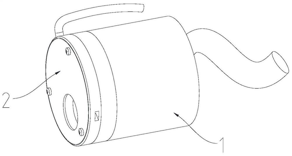
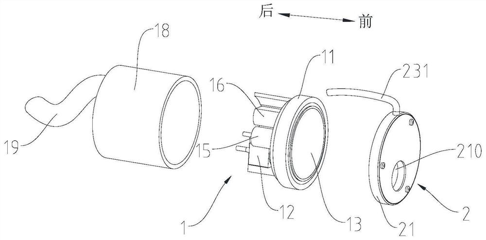
[0032] In this disclosure, unless otherwise stated, the orientation words used, such as "front", refer to the side that the lens of the vehicle-mounted visual collection device faces, and "rear" refers to the side opposite to "front". Specifically, refer to figure 2 In the directions indicated by the arrows in the middle, "inside" and "outside" refer to the inside and outside of the contours of the corresponding components. Specifically, for lenses, the side corresponding to "front" is "outside", and the side corresponding to "back" is The side is "inside". In addition, when the following description refers to the accompanying drawings, the same numerals i...


PUM


Abstract

The invention relates to a vehicle-mounted vision collection device and an unmanned vehicle, and the device comprises a body part which comprises a base, a vision collection part and a lens, wherein the vision collection part and the lens are installed on the base, and the lens is located in front of the vision collection part and is rotatably installed on the base; and a shielding part which comprises a shielding cover connected with the base, wherein a light hole corresponding to the position of the visual collection part is formed in the shielding cover, the shielding part further comprises a scraping piece fixed on the shielding cover, and the scraping piece is located in a cavity between the shielding cover and the lens and can clean the surface, close to the shielding part, of the lens when the lens rotates. The scraping part is matched with rotation of the lens to clean dirt on the surface of the lens, and the automatic cleaning effect is achieved; in the self-cleaning process, the visual area of the visual collection part cannot be shielded by the scraping part, and normal work of the visual collection part is guaranteed. And the scraping part is fixed on the shielding cover and is positioned in the cavity between the shielding cover and the lens, so that the scraping part is not exposed in the external environment for a long time, and the service life is not influenced.

Description

technical field [0001] The present disclosure relates to the technical field of vehicle-mounted electronic devices, and in particular, relates to a vehicle-mounted vision acquisition device and an unmanned vehicle. Background technique [0002] Unmanned vehicles, passenger vehicles with unmanned driving assistance systems, etc. are usually equipped with multiple on-board vision acquisition devices, such as cameras, lidar, etc., which are used to collect and monitor the external environment of the vehicle and provide reference for the driving of the vehicle. Taking the camera as an example, during the driving process, dirt in the natural environment, such as rain, snow, dust, leaves, shellac, etc., will adhere to the lens of the camera, affecting the camera's acquisition of the surrounding environment, thereby affecting the driving performance and security. In related technologies, the commonly used solution is to spray glass water on the lens and then blow it off with air. ...

Claims


Application Information

Patent Timeline
Patent Type & Authority Applications(China)
IPC IPC(8): H04N5/225G01M11/02G01N21/94B08B1/02
CPCG01M11/0278G01N21/94B08B1/02B08B1/005H04N23/50
Inventor 刘旸宁柯军李佳常鑫
Owner BEIJING SANKUAI ONLINE TECH CO LTD
Why Eureka
Try Eureka